^1 HARDWARE REFERENCE MANUAL ^2 MACRO CPU Board ^3 HRM for UMAC MACRO & MACRO Stack ^4 4Ax-602804-xHxx ^5 June 7, 2004 Single Source Machine Control Power // Flexibility // Ease of Use 21314 Lassen Street Chatsworth, CA 91311 // Tel. (818) 998-2095 Fax. (818) 998-7807 // www.deltatau.
Copyright Information © 2003 Delta Tau Data Systems, Inc. All rights reserved. This document is furnished for the customers of Delta Tau Data Systems, Inc. Other uses are unauthorized without written permission of Delta Tau Data Systems, Inc. Information contained in this manual may be updated from time-to-time due to product improvements, etc., and may not conform in every respect to former issues. To report errors or inconsistencies, call or email: Delta Tau Data Systems, Inc.
MACRO CPU Board Hardware Reference Manual Table of Contents INTRODUCTION .......................................................................................................................................................1 3U Product Configurations (General Description) ....................................................................................................2 MACRO CPU Specifications...............................................................................................................
MACRO CPU Board Hardware Reference Manual ii Table of Contents
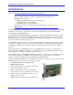
MACRO CPU Board Hardware Reference Manual INTRODUCTION The 3U MACRO-CPU board is the processor and MACRO interface board that is used in a 3U MACRO Station (in either UMAC MACRO or MACRO Stack configuration). Note: Three documents describe the operation of Delta Tau Data Systems Inc.
MACRO CPU Board Hardware Reference Manual The 3U MACRO Station can be configured in either of two fundamental assemblies – UMAC MACRO and MACRO Stack: • UMAC MACRO – In this configuration (once called Pack) the 3U-format boards are put together to communicate through a backplane bus called the UBUS. All boards are installed in a Euro-card rack.
MACRO CPU Board Hardware Reference Manual MACRO CPU Specifications Physical Specifications Size: Weight: 16cm x 10cm x 3.6cm (6.3" x 3.95" x 1.4") ½ lb. Temperature Operating: Storage: 0°C to 60°C (32°F to 140°F) 12°C to 82°C (10°F to 180°F) Humidity: 10% to 95%, non condensing Electrical Specifications Power: Introduction 1.5A @ +5V (±5%) (7.5W) Pertains to 8-channel configuration with a typical load of encoders.
MACRO CPU Board Hardware Reference Manual 4 Introduction
MACRO CPU Board Hardware Reference Manual CONFIGURATION AND HARDWARE SETUP The purchase of the 3U MACRO CPU board provides a 3U-format (100mm x 160mm) board with a DSP processor, MACRO ring circuitry, piggyback connectors onto which stack accessory boards can be mounted, and a backplane connector through which other 3U-format boards can be connected by means of a UBUS passive-backplane board.
MACRO CPU Board Hardware Reference Manual Board Jumper and Switch Setup The MACRO Station has two 16-way rotary switches on the MACRO CPU board that establish the station’s basic configuration on the MACRO ring. SW1 Rotary Switch Setting: SW1 establishes how many servo nodes, and which servo nodes, will be used on the MACRO station. It also establishes the mapping of MACRO node numbers to MACRO Station channel numbers. This mapping information will be important in establishing the software setup.
MACRO CPU Board Hardware Reference Manual Power Supply Check Jumper: Remove jumper E4 if you are not bringing a +/-12V to +/-15V supply into the Compact MACRO Station itself (5V only). If bringing these analog circuit supplies into the Compact MACRO Station, it is best to have jumper E4 on, so that the servo outputs are disabled if either of the analog supplies is lost.
MACRO CPU Board Hardware Reference Manual 8 Configuration and Hardware Setup
MACRO CPU Board Hardware Reference Manual JUMPER AND SWITCH CONFIGURATIONS Card Layout The Location columns of the following tables refer to the mapped locations shown in the drawings below: Note: Pin 1 of an E-point is masked by an X in white ink on the composite side and by a square solder pad on the solder side.
MACRO CPU Board Hardware Reference Manual E1: Watchdog Timer Disable Rev –105 and Rev –104 and Later Location Earlier Location B-1 F-1 Jumper Type Description Default 2-Pin Remove jumper to enable Watchdog Timer. Jump pins 1 and 2 to disable Watchdog Timer (for test purposes only). Not jumpered E2: CPU Mode Operation Rev –105 and Rev –104 and Later Location Earlier Location D-2 D-1 Jumper Type 3-Pin Description Jump pins 1 and 2 for firmware download through serial port.
MACRO CPU Board Hardware Reference Manual E40: MACRO Input (Fiber/Wired) Selector Rev –105 and Later Location B-3 Rev –104 and Jumper Earlier Location Type C-3 2-Pin Description Remove jumper to select MACRO wired (RJ45) input from J14. Jump pins 1 and 2 to select MACRO fiber optic input from U73.
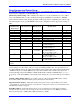
MACRO CPU Board Hardware Reference Manual Switch Configurations SW1: MACRO Slave Node Configure SW1 Setting # of Servo Channels MACRO Servo Station and Nodes Used Nodes Specified Channel Nos.
MACRO CPU Board Hardware Reference Manual SW2: MACRO Master Number Select 0: Commanded from Master IC # 0 1: Commanded from Master IC # 1 … F: Commanded from Master IC # F (15) Connector Summary J1: ~* J2: ~* J3: ~* J4: ~* J5: ~* J6: J7: J14, J17: P1: TB1: U73: JEXP_A: for interboard connection JEXP_B: for interboard connection JEXP_C: for interboard connection JISP: Factory configuration header JTAG/OnCE: Factory troubleshoot header JTHW: Multiplexer Port Connector JRS232: Serial Port Connector RJ45: MA
MACRO CPU Board Hardware Reference Manual 14 Jumper and Switch Configurations
MACRO CPU Board Hardware Reference Manual MACRO STATION CHARACTER DISPLAY The Compact MACRO Station has a single hexadecimal character display on the CPU/Interface Board that provides useful information as to the status of the station.
MACRO CPU Board Hardware Reference Manual 16 MACRO Station Character Display
MACRO CPU Board Hardware Reference Manual FIRMWARE UPDATES Downloading new firmware to the MACRO Station is a simple process once the MACRO board is setup properly. To download new firmware to the MACRO station, the user must have the following items: • 5V power supply • 2 jumpers • DB9 female to 10 pin header (any cable used for PMAC RS232 communications) • PC at the DOS prompt. • New firmware and necessary downloading batch files Make sure to power down the MACRO Station.
MACRO CPU Board Hardware Reference Manual 18 Firmware Updates
MACRO CPU Board Hardware Reference Manual CONNECTOR PINOUTS The schematic circuits shown in this section are for interface reference only. Subtle differences may exist between the circuits shown here and the actual hardware used. J6: (JTHW) Multiplexer Port Connector (26-pin head at Location D-3) Front View Pin # Symbol Function 1 2 3 4 5 6 7 8 9 10 11 12 13 14 15 16 17 18 19 20 21 22 23 24 25 26 GND GND DAT0 SEL0 DAT1 SEL1 DAT2 SEL2 DAT3 SEL3 DAT4 SEL4 DAT5 SEL5 DAT6 SEL6 DAT7 SEL7 N.C.
MACRO CPU Board Hardware Reference Manual Circuitry for J6- JTHW Interface J7: (JRS232) Serial Port Connector (10-pin Header at Location C-1) Front View Pin # 1 2 3 4 5 6 7 8 9 10 20 Symbol N.C. DTR TXD/ CTS RXD/ RTS DSR N.C.
MACRO CPU Board Hardware Reference Manual Circuitry for J7- JRS232 Interface J14, J17: MACRO Copper I/O (Opt C) (8 pin RJ45) Front View Pin # Symbol Function 1 DATA+ Data + Description Notes J17: DATA+ input. J14: DATA+ output. 2 DATAData Differential MACRO Signal J17: DATA- input. J14: DATA- output. 3 Unused Unused terminated pin See schematic below. 4 Unused Unused terminated pin See schematic below. 5 Unused Unused terminated pin See schematic below.
MACRO CPU Board Hardware Reference Manual P1: UBUS Interface Connector (96 pin EURO-Connector at F-1, 2, 3, 4) Front View on MACRO-CPU Card Pin # Row A Row B Row C 1 +5Vdc +5Vdc +5Vdc 2 GND GND GND 3 BD01 DAT0 BD00 4 BD03 SEL0 BD02 5 BD05 DAT1 BD04 6 BD07 SEL1 BD06 7 BD09 DAT2 BD08 8 BD11 SEL2 BD10 9 BD13 DAT3 BD12 10 BD15 SEL3 BD14 11 BD17 DAT4 BD16 12 BD19 SEL4 BD18 13 BD21 DAT5 BD20 14 BD23 SEL5 BD22 15 BS1 (GND) DAT6 BS0 (GND) 16 BA01 SEL6 BA00 17 BA03 DAT7 BA02 18 BX/Y SEL7 BA04 (n.c.
MACRO CPU Board Hardware Reference Manual U73: MACRO Fiber Optic Connector (Option A) (2 Socket SC-Style) Front View Pin # Symbol Function Description Notes 1 RX Fiber Input MACRO Ring Receiver 2 TX Fiber Output MACRO Ring Transmitter A. The fiber optic version of MACRO uses 62.5/125 multi-mode glass fiber optic cable terminated in an SC-style connector. The optical wavelength is 1,300nm. B. It is possible to adapt wire to fiber operation when using OPT A & C on the same MACRO-CPU board.
MACRO CPU Board Hardware Reference Manual 24 Connector Pinouts
MACRO CPU Board Hardware Reference Manual HARDWARE MEMORY MAP The values in this table represent the hardware locations associated with register-based transactions that occur in the 3U MACRO-CPU.
MACRO CPU Board Hardware Reference Manual 26 Hardware Memory Map
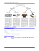
MACRO CPU Board Hardware Reference Manual ACCESSORIES Both the Turbo and the MACRO CPU boards can support either the Stack or the UMAC configuration. The systems are configured modularly with the selection of a series of accessory boards, some appropriate for the Stack, and some appropriate for the UMAC. These accessories are listed here. Each has its own manual for detailed description.
MACRO CPU Board Hardware Reference Manual Amplifiers – Analog ±10VDC Input (Brush Motors) Amplifiers – Digital PWM Input (brushless) Power Supplies – DC Input Power Supplies – AC Input UMAC Chassis Assemblies (Rack) Hybrid Stack/Pack Accessories (Legacy Systems Only) 28 4-Axis Analog ± 10V Input 4-Axis Analog ± 10V Input Linear Amplifier, 24VDC, PWM Amplifier, 48VDC, 0.