
Specifications


MACRO CPU Board Hardware Reference Manual
Table of Contents i
Table of Contents
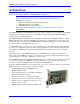
INTRODUCTION.......................................................................................................................................................1
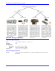
3U Product Configurations (General Description)....................................................................................................2
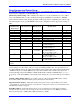
MACRO CPU Specifications....................................................................................................................................3
Physical Specifications .........................................................................................................................................3
Electrical Specifications .......................................................................................................................................3
CONFIGURATION AND HARDWARE SETUP....................................................................................................5
Board Hardware Setup ..............................................................................................................................................5
Board Jumper and Switch Setup................................................................................................................................6
Board Connections....................................................................................................................................................7
JUMPER AND SWITCH CONFIGURATIONS......................................................................................................9
Card Layout...............................................................................................................................................................9
E1: Watchdog Timer Disable ............................................................................................................................10
E2: CPU Mode Operation .................................................................................................................................10
E3: Serial Port Baud Rate .................................................................................................................................10
E4: Power Supply-Loss Control (±15Vdc Supply Monitor)...............................................................................10
E5: MACRO Received Signal Detect/Bypass Mode (Rev -105 and 106 only)...................................................10
E40: MACRO Input (Fiber/Wired) Selector......................................................................................................11
JP3: MACRO Loop Back Test Select for Copper only (Rev -104 and Earlier).................................................11
JP4: Reserved for Future Use ............................................................................................................................11
JP5-JP6: MACRO Copper EQ Select (Rev -104 and Earlier)............................................................................11
Switch Configurations.............................................................................................................................................12
SW1: MACRO Slave Node Configure................................................................................................................12
SW2: MACRO Master Number Select ...............................................................................................................13
Connector Summary................................................................................................................................................13
MACRO STATION CHARACTER DISPLAY......................................................................................................15
Hardware Re-Initialization......................................................................................................................................15
FIRMWARE UPDATES ..........................................................................................................................................17
BOARD CONNECTOR PINOUTS .........................................................................................................................19
J6: (JTHW) Multiplexer Port Connector.................................................................................................................19
J7: (JRS232) Serial Port Connector.........................................................................................................................20
J14, J17: MACRO Copper I/O (Opt C)..................................................................................................................21
P1: UBUS Interface Connector ...............................................................................................................................22
TB1: (JPWR) 4-Pin Terminal Block.......................................................................................................................22
U73: MACRO Fiber Optic Connector (Option A)..................................................................................................23
HARDWARE MEMORY MAP...............................................................................................................................25
ACCESSORIES.........................................................................................................................................................27