
Specifications


MACRO CPU Board Hardware Reference Manual
Configuration and Hardware Setup 5
CONFIGURATION AND HARDWARE SETUP
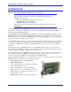
The purchase of the 3U MACRO CPU board provides a 3U-format (100mm x 160mm) board with a DSP
processor, MACRO ring circuitry, piggyback connectors onto which stack accessory boards can be
mounted, and a backplane connector through which other 3U-format boards can be connected by means
of a UBUS passive-backplane board.
The MACRO CPU board went through an extensive redesign in the –105 revision, because key
components on the –104 and older revisions became obsolete. Both the older and the newer versions are
described in this manual. The only system change required is a slight change in the DIP-switch
addressing of Acc-24E2x and Acc-51E backplane axis boards when using the new MACRO CPU
boards.
Note:
It is recommended that only the new MACRO CPU boards, which have stronger
backplane bus drivers, be used in UMAC pack configurations.
The 3U MACRO-CPU can be purchased in two physical configurations, distinguished by part number
prefix:
• 300-602804-10x provides the 3U MACRO-CPU board without a front plate. This configuration is
recommended for stack assemblies.
• 3R0-602804-10x provides the 3U MACRO-CPU board with a front plate. This configuration is
recommended for UMAC rack assemblies. The top and bottom plates are provided with the Acc-Px
rack.
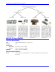
There are a few options available for the MACRO CPU board. One of the Options A or C must be
present on a MACRO CPU board to provide the actual MACRO ring interface circuitry; both may be
present:
Option A provides an SC-style fiber-optic transceiver to connect into the MACRO ring. Its main
component is the U73 transceiver.
Option C provides RJ-45 electrical input and output connectors for the MACRO ring. Its main
components are J14 and J17.
Option 10 permits a specified revision of the MACRO Station firmware to be installed in the flash
memory in the card. Without this option, the latest released revision is installed. A label on the flash
memory IC indicates the firmware revision installed at the factory (but not necessarily which revision is
presently installed in the IC). The presently installed revision can be ascertained by using the
MSVER{node #} command.
Board Hardware Setup
The hardware setup of the 3U MACRO CPU Board consists of the setting of two rotary switches, the
setting of several E-point jumpers on each board, followed by power supply and signal connections.
Note:
E-Point Jumper numbers are shown in white ink on the legend of each board. Pin
numbers for each number can be determined either from the legend on the
component side on the board, or by looking at the solder side of the board, where
pin 1 has a square solder pad.