
User's Manual


PMAC User Manual
Setting Up a Motor 83
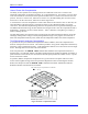
Backlash Tables
A backlash compensation table created with the DEFINE BLCOMP command can be used to create
backlash distances that vary with the position of the motor. Most often, this is used in conjunction with a
leadscrew compensation table to create the effect of a bi-directional leadscrew compensation table.
The value of backlash distance for a given motor position derived from the backlash table is added onto
the Ix86 constant backlash parameter. The backlash distance from the table at motor position 0 (home
position) is zero by definition, so if a backlash table is used, Ix86 should contain the amount of backlash
at the home position. The table then should hold the differences from this amount.
Note:
Typically, while the range and spacing of a backlash table will be the same as for
the leadscrew compensation table for the same motor, this is not required. Even
the presence of a leadscrew compensation table for a motor is not required to have
a backlash table for that motor.
The backlash table for a motor is only active if the most recent commanded direction of movement is
negative; it is still active if the motor is currently commanded to stand still but reached this position by
traveling in the negative direction. In operation, the table reads the present nominal motor position and
computes a weighted average of the two closest table entries, creating a first-order interpolation between
table points.
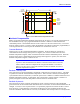
The backlash compensation is defined directly for a range of motor position starting a zero counts and
going in the position direction to the count length declared by the last argument in the DEFINE BLCOMP
command. The spacing between entries is this length divided by the number of entries (which is the first
argument in the command). The first entry in the table defines the correction at on spacing from the zero
position of the motor, the second entry at two spacings, and so on.
Outside this range, the uncorrected position is rolled over to within this range before the compensation is
done. This rollover occurs exactly as for leadscrew compensation tables.
The constant backlash parameter Ix86 is always (potentially) active. Backlash tables are (potentially)
active if I51 is set to 1; they are inactive if I51 is set to 0.
Example:
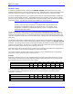
Imagine the calibration of an axis was performed against an accurate linear measurement device on the
load, working in both directions, and the following readings of the linear device for set positions of the
motor encoder (expressed in units of the motor encoder):
Motor Pos. (cts)
0 500 1000 1500 2000 2500 3000 3500
Load Pos.+ (cts)
0* 510 995 1492.5 1994 2497.5 3003.5 3500.5
Load Pos.- (cts)
5 516 998.5 1494 2000 2501 3010.5 3508.5
* Reference point; zero by definition
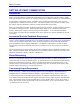
Only the compensation table works in the positive direction, so the entries in the compensation table
should be the negative of the difference between positive-going load position and motor position,
expressed in 1/16 counts:
Motor Pos. (cts)
0 500 1000 1500 2000 2500 3000 3500
Load - Motor (cts)
0* +10 -5 -7.5 -6 -2.5 +3.5 +0.5
Motor - Load (1/16 cts)
0* -160 +80 +120 +96 +40 -56 -8
* Reference point; zero by definition