
User's Manual


PMAC User Manual
84 Setting Up a Motor
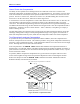
The compensation table definition to create these corrections would be:
DEFINE COMP 8,4000
-160 80 120 96 40 -56 -8 0
Notice that the first entry is for the correction at 500 counts, and the added last entry is 0, for the
correction at 4000 counts and 0 counts.
There is a 5-count backlash at motor position 0, so Ix86 should be set to 5*16, or 80.
The backlash table should contain the differences between negative-going load position and positive-
going load position, minus Ix86:
Motor Pos. (cts)
0 500 1000 1500 2000 2500 3000 3500
Load(-) - Load(+) (cts)
5 6 3.5 1.5 6 3.5 7 8
Load(-) - Load(+)-Ix86 (cts)
0* 1 -1.5 -3.5 1 -1.5 2 3
Load(-) - Load(+)-Ix86 (1/16 cts)
0* 16 -24 -56 16 -24 32 48
* Reference point; zero by definition
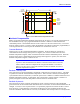
The backlash table definition to create these corrections would be:
DEFINE BLCOMP 8,4000
16 -24 -56 16 -24 32 48 0
Notice that the first entry is for the correction at 500 counts, and the added last entry is 0, for the
correction at 4000 counts and 0 counts.
Torque Compensation Tables
PMAC provides the capability to create a table of corrections as a function of motor position to the output
of the servo loop. Typically, this feature will be used with the servo loop in torque mode (whether or not
PMAC is also performing motor commutation), so this function is called torque compensation table.
The torque compensation tables are entered and operated much like the leadscrew compensation tables,
which provide a position correction. However, there are no cross-axis or multi-axis torque compensation
tables. The table belonging to a motor provides a torque correction to that motor as a function of that
motor’s position.
The torque compensation table for a motor is declared with the on-line command DEFINE
TCOMP{entries}, {count length} for the addressed motor. {entries} defines the number
of points in the table, and {count length} defines the span of the table in counts of the motor. The
spacing between entries in the table is therefore {count length} / {entries}. The first entry
in the table defines the correction at one spacing from the zero position of the motor, the second entry at
two spacings, and so on. The correction at motor zero position is zero by definition.
The correction is defined directly for the range of motor positions 0 to {count length}. For motor
positions outside this range, the position is rolled over to within this range before the correction is applied.
In this way, cyclic disturbances such as motor cogging torque can be compensated for. The correction at
the end of the table is equivalent to the correction at zero position; because the correction at zero position
is zero by definition, the last entry of any table intended to be rolled over should be zero also.
After the table definition command, the next {entries} constants sent to PMAC are put into the table
as table entries. The units of the entries in the table are the units of a 16-bit DAC, with range -32,768 to
+32,767, even if an output device of a different resolution is used. Corrections at points in between
entries of the table are linearly interpolated from the adjacent values in the table.
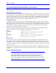
If the following table were entered:
#1
DEFINE TCOMP 8, 2000 ;Table of 8 entries over 2000 counts for motor 1
125 ;correction at 2000/8=250 counts is 125 DAC bits
-50 ;Correction at 500 counts is -50 DAC bits