
User's Manual


PMAC User Manual
Input/Output: Connecting PMAC to the Machine 41
INPUT/OUTPUT: CONNECTING PMAC TO THE MACHINE
Capabilities and Features
PMAC has extensive input and output capabilities, analog and digital, special-purpose and general-
purpose. The I/O has many features to ensure the integrity of the signals; as the different types of I/O are
introduced, the steps taken to improve the integrity of each type of I/O is explained.
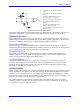
Quadrature Encoder Inputs (JMACH Port)
PMAC is equipped to take digital quadrature encoder signals at 0 to 5V levels as a standard feature. For
each DSPGATE IC in a PMAC configuration, four encoders can be attached.
Single-Ended vs. Differential
PMAC has differential line receivers for each encoder channel, but can accept either single-ended (one
signal line per channel) or differential (two signal lines, main and complementary, per channel). A
jumper for each encoder (E18-E21 and E24-E27) permits customized configurations, as described below.
The differential line receivers can accept up to +/-12V between main and complementary inputs, and +/-
12V between either input the GND reference voltage. Typically, 0 and +5V levels are used.
Single-Ended Encoders
With the jumper for an encoder set for single-ended, the differential input lines for that encoder are tied to
2.5V; the single signal line for each channel is then compared to this reference as it changes between 0
and 5V.
A
B
C
ENCODER 1
ENCODER 2
ENCODER 3
ENCODER 4
ENCODER
CONTROL
4
ENCODER
INPUTS
ANALOG
CONTROL
24-BIT
DATA BUS
16-BIT
ADDRESS BUS
DSP-GATE
ENCODER
SAMPLE
SERVO PHASE
SELECTABLE-FREQUENCY CLOCK INPUTS
SERIAL
DATA OUT
SERIAL
DATA IN
CLOCK
MUX
CONTROL
MUX
DAC 1
DAC 2
DAC 3
DAC 4
1
2
3
4
ADC
16 BIT
4
ANALOG
INPUTS
4
ANALOG
OUTPUTS.
16 BIT
RESOLUTION
LD
LD
LD
LD
ADC SHIFT REGISTERS (4)
DAC SHIFT REGISTERS (4)
A
B
C
A
B
C
A
B
C
AENA 1-4
EQU 1-4
OPTO
ISOLATION
FLAG
CONTROL
HOME 1-4
+LIMIT 1-4
-LIMIT 1-4
FAULT 1-4
INPUT
FLAGS
OUTPUT
FLAGS
ACCESSORY BOARD
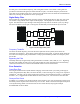
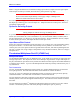
Figure 1 PMAC Motion Controller Custom Gate Array IC