
User's Manual


PMAC User Manual
42 Input/Output: Connecting PMAC to the Machine
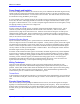
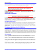
Connect pin 1 to 2 to tie differential line to
+2.5V
Connect pin 2 to 3 to tie differential line to
+5V
(Reversible socketed SIP on PMAC2)
Tie to +2.5V when no connection
Tie to +2.5V for single-ended encoders
Don't care for differential line driver
encoders
Tie to +5V for complementary open-
collector encoders (obsolete)
Tie to +5V to support external XOR loss of
encoder circuitry
Figure 2 PMAC Encoder Input Circuitry
When using single-ended TTL-level digital encoders, the differential line input should be left open, not
grounded or tied high; this is required for the PMAC differential line receivers to work properly.
Differential Encoders
Differential encoder signals can enhance noise immunity by providing common-mode noise rejection.
Modern design standards virtually mandate their use for industrial systems, especially in the presence of
PWM power amplifiers, which generate a great deal of electromagnetic interference.
Open-Collector Differential
There are two types of differential encoder signals. The first has simple open-collector drivers (or
equivalent) on both the main and complementary channels. For this type of encoder, the jumper must be
set up for differential mode to provide pull-up resistors on both inputs.
Differential Line Drivers
The second type of differential encoder format (and the one that is strongly recommended) is the
differential line driver on both signals. For this type of encoder, it does not matter what the jumper
setting is; most will leave the jumper in the default setting.
Termination Resistors
When driving the encoder signals over a long cable (10 meters or more), to reduce the ringing on
transitions, add termination resistors between the main and complementary lines. PMAC provides
sockets for resistor packs for this purpose. The optimum value of the termination resistor is system
dependent, but 330 ohms is a good starting point.
Analog Encoders
PMAC can take analog voltage-source encoder inputs into its differential line receivers if the drivers have
enough capability to work against a 470 ohm pull-up resistor and the maximum differential voltage the
line receiver sees is between 2 and 12V. For a single-ended analog signal, the complementary channel
should be tied to GND to provide proper transitions as the voltage signal goes positive and negative. It is
better, but not required, to jumper the input for single-ended.
For a differential analog encoder, the two signals for each channel are wired in just as for a digital
differential encoder. It is better, but not required, to jumper the input for differential. In this case, the
12V input limit is a peak-to-peak measurement.