
User's Manual


PMAC User Manual
Input/Output: Connecting PMAC to the Machine 43
Power Supply and Isolation
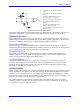
In the basic configuration of PMAC, the encoder circuitry is not isolated from the PMAC digital circuitry
and the signals are referenced to the PMAC digital common level GND. Typically, the encoders in this
case are powered from the PMAC +5V lines with a return on GND. The total encoder current draw must
be considered in sizing the PMAC power supply.
It is also possible to use a separate supply for the encoders with non-isolated signals connected to PMAC.
In this case, the return of the supply should be connected to the digital common GND on PMAC to give
the signals a common reference. The +5V lines of separate supplies should never be tied together, as they
will fight each other to control the exact voltage level.
Isolated Encoder Signals
In many systems, the encoder circuitry is optically isolated from the PMAC digital circuitry. This is
common in systems with long distances from the encoder to the controller (> 10m or 30 ft) and/or
systems with very high levels of electrical noise. Isolation can be achieved using the Acc-8D Opt 6 4-
channel encoder isolator board. With an isolated encoder, a separate power supply is required for the
encoders to maintain isolation, and the return on the supply must not be connected to the digital common
GND, or the isolation will be defeated.
Simulated Encoder Signals
Special consideration must be given to systems that have a simulated encoder signal provided from a
resolver-to-digital converter in a brushless motor amplifier. Usually in these systems, the encoder signals
are referenced to the amplifier’s signal return, which in turn is connected to the PMAC analog common
AGND. The best setup in these cases is to isolate the simulated encoder signal from the PMAC digital
circuitry with the Acc-8D Opt 6 isolator board or similar module. This will keep full isolation between
the PMAC digital circuitry and the amplifier.
If isolation of the simulated encoder signals is not feasible, the PMAC digital circuitry and the amplifier
signal circuitry (including the PMAC analog circuitry) must be well tied together to provide a common
reference voltage. Do this by putting jumpers on PMAC E-Points E85, E87, and E88, tying the digital
and analog circuits on PMAC together, and therefore the analog signal circuits. Avoid having the
simulated encoder cables providing the only connection between the circuits. This can result in lost
signals from bad referencing, or even component damage from ground loops.
Wiring Techniques
There are several important techniques in the wiring of the encoders that are important for noise
mitigation. First, the encoder cable should be kept physically separate from the motor power cable if
possible. Second, both of these cables should be shielded, the motor cable to prevent noise from getting
out, and the encoder cable to prevent noise from getting in. These shields should be grounded at the
inward end only, that is, to the device that is itself tied to a ground.
Twisted Pairs
A third important noise mitigation technique is to twist the leads of the complementary pairs around each
other. With these twisted pairs, what noise does get in tends to cancel itself out in opposite halves of the
twist.
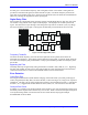
Encoder Signal Sampling
After the front-end processing through the differential line receivers, the encoder signals are sampled
digitally at a rate determined by the SCLK (encoder sampling clock) frequency. SCLK is divided down
from the master clock frequency by an amount determined by jumpers E34 to E38. The default setting is
E34 ON, which gives SLCK half the frequency of the master clock, which on the standard board is about
10 MHz.