
User's Manual


PMAC User Manual
48 Input/Output: Connecting PMAC to the Machine
Optically Isolated Analog Outputs (JMACH Port)
PMAC provides high-precision analog outputs on the JMACH machine connectors that are used to
command servo amplifiers as a velocity command, a torque command, or phase current commands (in
pairs). Each channel of PMAC provides complementary DAC and DAC/ outputs, operating from 16-bit
digital-to-analog converters. Each output has a range of -10V to +10V, providing a resolution of
300µV/bit.
Connections
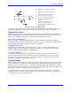
If the amplifier has a single-ended input, DACn should be used as the command line, and AGND as the
return. If the amplifier has a differential input, DACn should be used as the command line and DACn/ as
the return. The common of the amplifier input should still be tied to the PMAC AGND in this case.
Isolation
The analog command output circuitry is optically isolated from the digital logic circuitry on PMAC.
Usually the analog circuitry will get its power from the amplifier (most amplifiers provide +/- 15V for
this purpose). Use Jumpers E85, E87, E88, and E90 to jumper the power supply for the analog circuitry
from the digital side of the board, but this defeats the optical isolation; it is not recommended for any
high-power or high-noise environment, especially when PMAC is electrically connected to a host
computer, either by backplane bus or by non-isolated serial cable.
Drive Capability
The analog outputs are intended to drive high-impedance inputs with no significant current draw. The
220Ω output resistors will keep the current draw lower than 50mA in all cases and prevent damage to the
output circuitry, but any current draw above 10mA can result in noticeable signal distortion.
General-Purpose Use
Any analog output not used for dedicated servo purposes may be utilized as a general-purpose analog
output. Usually, this is done by defining an M-variable to the digital-to-analog-converter register
(suggested M-variable definitions M102, M202, etc.), then writing values to the M-variable.
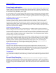
General-Purpose Digital Inputs and Outputs (JOPTO Port)
The PMAC JOPTO connector (J5 on PMAC PC, Lite, and VME) provides eight general-purpose digital
inputs and eight general-purpose digital outputs. Each input and each output has its own corresponding
ground pin in the opposite row. The 34-pin connector was designed for easy interface to OPTO-22 or
equivalent optically isolated I/O modules. Delta Tau's Accessory 21F is a six-foot cable for this purpose.
The PMAC STD has a different form of this connector from the other versions of PMAC. Its JOPT
connector (J4 on the base board) has 24 I/O, individually selectable in software as inputs or outputs. The
rest of this discussion does not pertain to the PMAC STD port, unless specifically mentioned. Refer to
the PMAC STD Hardware Reference Manual for details on its JOPT port.
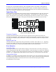
Software Access
These inputs and outputs are typically accessed in software through the use of M-variables. In the
suggested set of M-variable definitions, variables M1 through M8 are used to access outputs 1 through 8,
respectively, and M11 through M18 to access inputs 1 through 8, respectively. This port maps into the
PMAC memory space at Y address $FFC2.
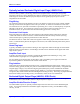
Standard Sinking Outputs
CAUTION:
Having Jumpers E1 and E2 set wrong can damage the IC.