
User's Manual


PMAC User Manual
50 Input/Output: Connecting PMAC to the Machine
Non-Multiplexed Uses
If none of these accessory boards is used, the inputs and outputs on this port may be used as discrete, non-
multiplexed I/O. They map into the PMAC processor space at Y address $FFC1. The suggested M-
variable definitions for this use are M40 to M47 for the eight outputs and M50 to M57 for the eight
inputs. The Acc-27 Optically Isolated I/O board buffers the I/O in this non-multiplexed form, with each
point rated to 24V and 100mA.
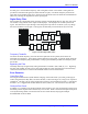
Control-Panel Port I/O (JPAN Port)
The JPAN connector (J2 on PMAC PC, Lite, VME, and top board of PMAC STD) is a 26-pin connector
with dedicated control inputs, dedicated indicator outputs, a quadrature encoder input, and an analog
input. The control inputs are low true with internal pull-up resistors. They have predefined functions
unless the control-panel-disable I-variable (I2) has been set to 1. If this is the case, they may be used as
general-purpose inputs by assigning M-variables to their corresponding memory-map locations (bits of Y
address $FFC0).
Discrete Inputs
Command Inputs
JOG-/, JOG+/, PREJ/ (return to pre-jog position), and HOME/ affect the motor selected by the FDPn/
lines (see below). STRT/ (run), STEP/, STOP/ (abort), and HOLD/ (feed hold) affect the coordinate
system selected by the FDPn/ lines.
Selector Inputs
CAUTION:
Do not change the selector inputs while holding one of the jog inputs low.
Releasing the jog input then will not stop the previously selected motor. This can
lead to a dangerous situation.
The four low-true BCD-coded input lines FDP0/ (LSBit), FDP1/, FDP2/, and FDP3/ (MSBit) form a low-
true BCD-coded nibble that selects the active motor and coordinate system (simultaneously). These are
usually controlled from a single 4-bit motor/coordinate-system selector switch. The motor selected with
these input lines will respond to the motor-specific inputs. It will also have its position following
function turned on (Ix06 is set automatically to 1.); the motor just de-selected has its position following
function turned off (Ix06 is set automatically to 0.).
Alternate Use
The discrete inputs can be used for parallel-data servo feedback or master position if I2 has been set to 1.
The Acc-39 Handwheel Encoder Interface board provides 8-bit parallel counter data from a quadrature
encoder to these inputs. Refer to the Acc-39 manual and the Parallel Position Feedback Conversion
sections under Setting up a Motor in this manual for more details on processing this data.
Reset Input
Input INIT/ (reset) affects the entire card. It has the same effect as cycling power or a host $$$
command. It is hard-wired, so it retains its function even if I2 is set to 1.
Handwheel Inputs
The handwheel inputs HWCA and HWCB can be connected to the second encoder counter on PMAC
with jumpers E22 and E23. If these jumpers are on, nothing else should be connected to the Encoder 2
inputs. The signal can be interpreted either as quadrature or as pulse (HWCA) and direction (HWCB),
depending on the value of I905. I905 also controls the direction sense of this input. Make sure that the
Encoder 2 jumper E26 is set for single ended signals, connecting pins 1 and 2.