
User's Manual


PMAC User Manual
Setting Up a Motor 63
Parallel-Data Position
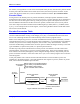
Ix10 can specify two types of feedback. If the absolute position data is presented to PMAC as a parallel
word, usually through an Acc-14 I/O board, then the address specified in the low 16 bits of Ix10 is the
address of the 'Y' PMAC register that holds this data (e.g., $FFD1). The high eight bits of Ix10 specify
the number of bits to use at this register (and potentially the next higher register as well). The most
significant bit specifies whether the quantity is to be treated as a signed or unsigned value and the second
most significant bit (bit 22) specifies whether the data comes from an X-register or a Y-register.
Valid values for the number of bits in this mode are 8 to 48 ($08 to $30). If the most significant bit (value
$80) is set to 1, giving a range for the high eight bits of $88 to $B0, the number read from the sensor is
treated a signed quantity, with a range of -(2
N-1
) to +2
N-1
-1, where N is the number of bits. If the
MSBit of Ix10 is zero, the sensor value is treated as an unsigned quantity, with a range of 0 to 2
N
-1.
Virtually all parallel I/O sources map into Y-registers in PMAC, so usually bit 22 (X/Y specification) is
set to 0 to specify a Y data source.
Example:
For a 22-bit absolute encoder on Port B of the first Acc-14 (Y:$FFD1) to be read as an unsigned quantity,
Ix10 would be set to $16FFD1 (16 hex is 22 decimal); to be read as a signed quantity, Ix10 would be set
to $96FFD1. For a 32-bit absolute sensor with the low 24 bits at Port A of the first Acc-14 (Y:$FFD0)
and the high eight bits at Port B (Y:$FFD1) to be read as an unsigned quantity, Ix10 would be set to
$20FFD0 (20 hex is 32 decimal); to be read as a signed quantity, Ix10 would be set to $A0FFD0.
Note:
A sensor with parallel data output is not necessarily an absolute sensor. Laser
interferometers often present their position data in parallel form, but they are
incremental sensors and a motor using one for position feedback still must be
homed. Ix10 should be left at 0 (no absolute power-on read) for any incremental
sensors.
Resolver Position
The other type of power-on position data that can be specified with Ix10 is serial data from an Acc-8D
Option 7 resolver-to-digital (R/D) converter board brought in through the thumbwheel multiplexer port.
In this format, the low 16 bits of Ix10 specify the multiplexed address on this port, a value from 0 to 256
decimal matching the address set on the board with DIP switches. (Multiplexer addresses are even
numbers ranging from 0 to 254; a value of 256 ($0100) should be used to specify multiplexer address 0,
because PMAC interprets a value of 0 to mean no absolute power-on position read).
The high eight bits of Ix10 contain a value from 0 to 7 specifying the location of the particular R/D
converter at that multiplexer address — there are potentially eight at each multiplexer address. In
addition, the most significant bit (value $80) specifies whether the position is to be treated as a signed or
unsigned quantity. If the MSBit is set to 0, the value read from the resolver is treated as an unsigned
quantity, with a range of 0 to 4095; if the MSBit is set to 1, the value is treated as a signed quantity, with
a range of -2048 to 2047.
For example, to use an R/D at location 3 of multiplexer address 2, treating the value as an unsigned
quantity, Ix10 would be set to $030002; treating the value as a signed quantity, Ix10 would be set to
$830002. To use an R/D at location 0 of multiplexer address 0, treating the value as an unsigned
quantity, Ix10 would be set to $000100; treating the value as a signed quantity, Ix10 would be set to
$800100.