
User's Manual


PMAC User Manual
64 Setting Up a Motor
Geared Resolvers
Typically, a single resolver on the back of the motor is not sufficient to determine power-on position. If
true power-on position information is required, a set of geared resolvers is used, each one geared down to
a slower speed, and therefore a coarser resolution, than the resolver before it was in the chain. The first
resolver, usually on the back of the motor and rotating with the motor, turns the fastest and has the highest
resolution. It is called the fine resolver or the first resolver. The last resolver in the gear chain turns the
slowest and has the lowest resolution. It should never turn more than one revolution — one electrical
cycle, really — and it is called the coarse resolver.
Theoretically, any number of geared resolvers can be used to establish power-on position. In practice,
most systems use two or three resolvers. In a two-resolver system, these are called the fine and coarse
resolvers. In a three-resolver system, they are called the fine, medium, and coarse resolvers. Since
PMAC can interface to both two- and three-resolver systems, the terminology first resolver or primary
resolver will be used for the fine resolver connected directly to the motor shaft. The resolver geared
down from the first resolver — coarse in a two-resolver system, medium in a three-resolver system —
will be called the second or secondary resolver. The next resolver will be called the third resolver.
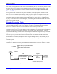
If a set of geared resolvers is to be used to determine power-on position with PMAC, variables I9x, and
possibly I8x must be changed from their default values of zero as well. The second resolver must be
connected to the R/D converter at the next higher location at the same multiplexer address than the
primary resolver. I9x represents the gear ratio between the primary and secondary resolvers. It must be
an integer number. If the second resolver were geared down from the primary resolver by a 16:1 ratio,
I9x would be set to 16. A value of 0 for I9x tells PMAC that there is no secondary resolver.
If there is a third resolver geared down from the second resolver, I8x is used to specify the gear ratio
between the second and third resolvers. The third resolver must be connected to the R/D converter at the
next higher location at the same multiplexer address than the second resolver. It must be an integer
number. If the ratio between the two were 36:1, I8x would be set to 36. A value of 0 for I8x tells PMAC
that there is no third resolver.
Even in a geared-resolver system, the most significant bit of Ix10 determines whether the combined
quantity will be treated as a signed or unsigned value. If it is to be treated as unsigned, the zero position
should be set up past the negative end of travel, so power-up position cannot be to the negative side of
zero. If it is to be treated as signed, the zero position should be in the normal range of travel; setting it in
the middle of travel maximizes the usable range of the axis.
On any motor using a resolver or resolvers for position feedback, all position information used in the
servo loop after the initial power-on read comes through the quadrature signals generated by the R/D
converter for the primary resolver, counted in one of the PMAC encoder counters. The software setup to
support this (Ix03, Ix04, conversion table) is the same as for a real quadrature encoder. There is no need
to use the quadrature signals generated from the second or third resolvers for the motor.
Axis Offset
What if the absolute sensor’s zero position is not where the axis’ zero position for programming purposes
should be? This is a very common occurrence, both because it is difficult to line up the sensor exactly,
and because the zero position of the sensor typically must be outside the range of travel if the position
information is treated as an unsigned value.
The difference between sensor (motor) zero and axis zero can be set by the axis offset parameter of the
axis definition statement for the axis. This parameter, with units of counts, should contain the axis
position when the sensor position is zero. It is independent of the axis scale factor (counts per
engineering unit) in the same axis definition statement.