
User's Manual


PMAC User Manual
Setting Up a Motor 69
ADC1: $C006 ADC9: $C026
ADC2: $C007 ADC10: $C027
ADC3: $C00E ADC11: $C02E
ADC4: $C00F ADC12: $C02F
ADC5: $C016 ADC13: $C036
ADC6: $C017 ADC14: $C037
ADC7: $C01E ADC15: $C03E
ADC8: $C01F ADC16: $C03F
A typical setup word for an A/D register would be $10C006, which provides the conversion of the
ADC1 register. With A/D conversion, there is no software extension performed, so rollover should not be
permitted.
The result is placed in the X-register of the entry, scaled so that there are 19 bits of integer (the highest
three bits are simply sign-extended), and five bits of fraction (the fraction is always zero).
Integrated Analog
It is possible to use the conversion table to integrate an analog input or equivalent. This is done with
conversion format $50, instead of the $10 used for normal (un-integrated) analog conversion. The
address of the A/D source register is specified just as for the $10 format. An entry to integrate the input
of ADC1 would be $50C006.
Bias Term
The integrated analog format requires a second entry to specify the bias of the A/D. This is a signed
quantity, with units of 1/256 of the LSBit of the 16-bit A/D converter. For example, if there were an
offset in 16-bit ADC of five LSBits, this term would be set to 1280. If no bias is desired, a zero value
should be entered here. This term permits reasonable integration, even with an analog offset.
Result Format
The integrated result is placed in the X-register of the second line of the entry, with 19 bits of integer and
five bits of fraction (the fraction is always zero). Because the input data has 16 bits (this high 16 bits of a
24-bit word), at the maximum range of the input, there is only a 3-bit (8-times) extension of the input into
this integrated register, with the integration performed every servo cycle. Therefore, whatever task uses
this information must look at the integrated register at least once every eight servo cycles to handle
potential rollover situations. This is no problem for the automatic servo-loop uses of the information
(master or feedback), but it could be a problem in a background task.
The integrated result is set to zero automatically on power-up/reset, and the integration function starts
immediately afterward. Any value may be written to the result register at any time (usually through an
M-variable); make sure that nothing using the register at the time could be adversely affected by changing
the value of this register.
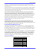
Integrated Analog Feedback
X-Words Y-Words
1. Intermediate data 1. Source and process:
Bits 0-15: Y-Address of source data
Bits 16-23: = $50
2. Converted data:
Bits 0-4: Fractional Bits
Bits 5-23: Integer Bits
2. Bias Term: 1/256 bit of 16-bit ADC
Uses of Integrated Analog
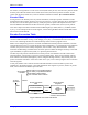
There are several possible uses of this format. First, an analog velocity sensor such as a tachometer could
be used to provide position-like information to the PMAC servo loop (remember that the velocity loop
expects position information). For example, consider an axis that has a motor with a tachometer, a linear
encoder on the load for accuracy, and a current-loop amplifier for high responsiveness. It is difficult to