DELTA TAU Data Systems, Inc. PMAC Programmable Multi-Axis Controller ^3QuickReference Quick Reference Fall 2002 ^4xxx-REFERE-ENCE Power // Flexibility // Cost Effectiveness // Customer Service // Ease of Use 21314 Lassen Street Chatsworth, CA 91311 // Tel. (818) 998-2095 Fax. (818) 998-7807 // www.deltatau.
Copyright Information © 2003 Delta Tau Data Systems, Inc. All rights reserved. This document is furnished for the customers of Delta Tau Data Systems, Inc. Other uses are unauthorized without written permission of Delta Tau Data Systems, Inc. Information contained in this manual may be updated from time-to-time due to product improvements, etc., and may not conform in every respect to former issues. To report errors or inconsistencies, call or email: Delta Tau Data Systems, Inc.
1.0 - INTRODUCTION TO PMAC_____________________________________________1 1.1 - About this manual ____________________________________________________________________________ 1 1.2 - Description of PMAC _________________________________________________________________________ 1 1. 3 - Types of PMAC _____________________________________________________________________________ 2 1.3.1 - PMAC(1) PC or PMAC(1) VME features _______________________________________________________ 2 1.3.
2.4 - The WATCH and POSITION windows _________________________________________________________ 15 2.5 - Uploading and Downloading files_______________________________________________________________ 15 2.6 - Using MACRO names and Include Files_________________________________________________________ 15 2.7 - Downloading compiled PLCCs ________________________________________________________________ 15 2.8 - The PID Tuning Utility _______________________________________________________________________ 16 2.
4.3.2 - P-Variables______________________________________________________________________________ 30 4.3.3 - Q-Variables _____________________________________________________________________________ 31 4.3.4 - M-Variables _____________________________________________________________________________ 31 4.3.5 - Array capabilities _________________________________________________________________________ 32 4.3.6 - Operators _______________________________________________________________________________ 33 4.3.
.0 - PLC PROGRAMS ___________________________________________________57 6.1 - Entering a PLC Program _____________________________________________________________________ 58 6.2 - PLC Program Structure ______________________________________________________________________ 58 6.3 - Calculation Statements _______________________________________________________________________ 58 6.4 - Conditional Statements_______________________________________________________________________ 59 6.4.
1.0 - Introduction to PMAC 1.1 - About this manual This manual is intended for first time users of the PMAC motion control. It is oriented to the PMAC(1) family of motion controls and it does not cover other PMAC families: PMAC2, Turbo PMAC(1), Turbo PMAC2, MACRO or UMAC. The subjects illustrated could be used as a quick informative features description or as a roadmap for a more advanced learning through the main documentation.
1.0 - Introduction to PMAC 1. 3 - Types of PMAC 1.3.
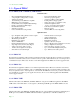
1.0 - Introduction to PMAC PMAC Types PMAC PC PMAC Lite Mini PMAC PMAC STD PMAC Pack PMAC VME Turbo PMAC PC Turbo PMAC VME Turbo PMAC2 3U Turbo PMAC2 PC Turbo PMAC2 PC Ultralite UMAC Turbo System Some PMAC types have been omitted from this page. Pictures are not in the same scale.
1.0 - Introduction to PMAC 1.3.6 – Mini-PMAC Recommended for applications with one or two channel requirements in either a PC based or stand alone environment. The Dual-ported RAM option in a Mini-PMAC is on-board. Two extra full encoder channels (for a total of 4 on-board) could be used for dual feedback applications or, with the two optional voltage-to-frequency (V/F) converters, for stepper drivers or hybrid amplifiers control. There is no control panel port or bus interrupt in the Mini-PMAC board.
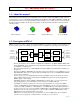
1.0 - Introduction to PMAC 1.4 – PMAC(1) connectors and indicators 1.4.1 – Display Port Outputs (JDISP Port) The JDISP connector (J1) allows connection of the ACC-12 or ACC-12A liquid crystal displays, or of the ACC-12C vacuum fluorescent display. Both text and variable values may be shown on these displays through the use of the DISPLAY command, executing in either motion or PLC programs. 1.4.
1.0 - Introduction to PMAC 1.5 - Working with PMAC When used for the first time the card must be configured for a specific application, using both hardware and software features, in order to run that application properly. PMAC is shipped from the factory with defaults set in hardware and software set up to be satisfactory for the most common application types.
1.0 - Introduction to PMAC 1.
1.0 - Introduction to PMAC 1.6.1 - Single Character I/O Bringing in a single character from, or sending out a single character to, the serial port or host port (PC or STD) is the highest priority in PMAC. This task takes only 200 nsec per character, but having it at this high priority ensures that the host cannot outrun PMAC on a character-by-character basis. This task is never a significant portion of PMAC's total calculation time.
1.0 - Introduction to PMAC 1.6.5 - Real-Time Interrupt Tasks The real-time interrupt (RTI) tasks are the fifth highest priority on PMAC. They occur immediate after the servo update tasks at a rate controlled by parameter I8 (every I8+1 servo update cycles). There are two significant tasks occurring at this priority level: PLC 0 / PLCC0 and motion program move planning.
1.0 - Introduction to PMAC 1.6.7 - Observations: - PMAC has an on-board "watchdog timer" circuit whose job it is to detect a number of conditions that could result in dangerous misfunction. At the default settings, if the RTI frequency were to drop below about 50 Hz or the background cycle is not performed at least every 512 RTI cycles, the timer would trip.
1.0 - Introduction to PMAC 1.6.8 - Priority Level Optimization PMAC will usually have enough speed and calculation power to perform all of the tasks asked of it without the user having to worry. Some applications will put a large demand on a certain priority level and to make PMAC run more efficiently some priority level optimization should be done.
Page - 12
2.0 - PMAC Executive program, PEWIN PEWIN enables you to configure, control and trouble-shoot your PMAC (s). PEWIN is designed as a development tool for creating and managing PMAC implementations. It provides a terminal interface to the PMAC and a text editor for writing and editing PMAC motion programs and PLC programs.
2.0 - PMAC Executive program, PEWIN 2.
2.0 - PMAC Executive program, PEWIN 2.4 - The WATCH and POSITION windows The position window is accessed through the “Position” command of the View pull-down menu, ALT+V and P from the terminal window. It is a very convenient way to continuously check PMAC parameters such as position velocity and following error. Right-clicking on this window allows the items selections as well as its format and update period. The “Watch” window of the same View menu performs a very similar function.
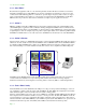
2.0 - PMAC Executive program, PEWIN 2.8 - The PID Tuning Utility This function is accessible from the terminal window by pressing ALT+C for the Configure pull-down menu and T for tuning. The Autotuning feature allows finding the PID parameters with virtually no-effort from the user. The parameters are, in most cases, very close to optimal and in some cases require further fine-tuning by the user. In this screen press the Page-Up or Page-Down keys on the keyboard to select the motor number.
2.0 - PMAC Executive program, PEWIN Second Interaction h i k j h) i) j) k) The calculated bandwidth could be increased up to three times. Uncheck the “Auto Select bandwidth” this time. Add the feed forward parameters as necessary. Add the integral actions function as necessary. Perform the second pass of the Auto Tuning. After completed remember to select “Implement Now” to activate the selected parameters.
2.
3.0 - Installing and Configuring PMAC 3.1 - Jumpers Setup On the PMAC, you will see many jumpers (pairs of metal prongs), called E-points (on the bottom board of the PMAC-STD they are called W-points). Some have been shorted together; others have been left open. These jumpers customize the hardware features of the board for a given application. It is strongly recommended to check each jumper configuration using the appropriate hardware reference for the particular PMAC being set.
Installing and Configuring PMAC 3.3 - Establishing Host Communications Either the Executive or Setup program can be used to establish initial communications with the card. Both programs have menus that allow you to tell the PC where to expect to find the PMAC and how to communicate with it at that location. If you tell it to look for PMAC on the bus, you must also tell it PMAC's base address on the bus (this was set up with jumpers on PMAC).
Installing and Configuring PMAC 3.4 - Connections Typically, the user connections are actually made to a terminal block that is attached to the JMACH connector by a flat cable (Accessory 8D or 8P). The pinout numbers on the terminal block are the same as those on the JMACH connector for PMAC-PC.
Installing and Configuring PMAC 3.6.1 - Disabling the overtravel limits flags If no overtravel limits are intended to be used, they must be disabled through a change of the variable Ix25. On the terminal window the following commands will disable the limits functions for all 8 motors. Select the motor numbers as appropriate. The OR ( | ) bit-by-bit function used here is accessible by pressing shift + ”\” in the computer’s keyboard.
Installing and Configuring PMAC 3.6.4 - PMACPack and PMAC2 flag inputs The PMACPack and PMAC2 interface accessories include a bipolar opto-isolating circuitry (chip PS-2705-4NEC) for flag and amplifier fault connections: Flag Return +V Flag Return Signal Sinking Signal (Gnd) Gnd Signal Sourcing Signal (+V) Examples: 3.6.
Installing and Configuring PMAC Connect the A and B (quadrature) encoder channels to the appropriate terminal block pins. For encoder 1, the CHA1 is pin 25, CHB1 is pin 21. If you have a single-ended signal, leave the complementary signal pins floating -- do not ground them. However, if single-ended encoders are used, please check the settings of the jumpers E18 to E21 and E24 to E27. For a differential encoder, connect the complementary signal lines -- CHA1/ is pin 27, and CHB1/ is pin 23.
Installing and Configuring PMAC format requires some parameter changes on PMAC; (see Ix02 and Ix25). Jumper E17 controls the polarity of the direction output; this may have to be changed during the polarity test. This magnitude-and-direction mode is suited for driving servo amplifiers that expect this type of input, and for driving voltage-to-frequency (V/F) converters, such as PMAC's ACC-8D Option 2 board, for running stepper motor drivers.
Installing and Configuring PMAC 3.
Installing and Configuring PMAC 3.9 - Software Setup PMAC has a large set of Initialization parameters (I-variables) that determine the "personality" of the card for a specific application. Many of these are used to configure a motor properly. Using PEWIN follow these steps for Software Setup: 1) Fully reset PMAC to assure a clean memory configuration before start: $$$*** P0..1023=0 Q0..1023=0 M0..1023->* M0..
Page - 28
4.0 - Programming PMAC Programming PMAC is very simple; the ease of use and power is based in the following features: - A clever interrupt-driven scheme allows every task, each motion program and PLC, to run independently of each other. Pointer M-variables allow monitoring virtually any register in PMAC’s memory from different sources: motion programs, PLCs or the host computer. Communications are continuously activated. At any moment, any variable or status command could be interrogated.
4.0 - Programming PMAC 4.2 - Buffered (Program) Commands As their name implies, buffered commands are not acted on immediately, but held for later execution. PMAC has many program buffers -- 256 regular motion program buffers, 8 rotary motion program buffers (1 for each coordinate system), and 32 PLC program buffers. Before commands can be entered into a buffer, that buffer must be opened (e.g. OPEN PROG 3, OPEN PLC 7).
4.0 - Programming PMAC P-variables are general-purpose user variables. They are 48-bit floating-point variables at fixed locations in PMAC's memory, but with no pre-defined use. There are 1024 P-variables, from P0 to P1023. A given P-variable means the same thing from any context within the card; all coordinate systems have access to all P- variables (contrast Q-variables, which are coupled to a given coordinate system, below). This allows for useful information passing between different coordinate systems.
4.
4.0 - Programming PMAC It is possible to use a set of P-variables as an array. To read or assign values from the array, simply replace the constant specifying the variable number with an expression in parentheses. Example: P1=10 P3=P(P1) ; Array index variable ; Same as P3=P10 To write to the array M-variables must be used. An M-variable defined to the corresponding P-variable address will allow changing any P-variable and therefore the contents of the array.
4.0 - Programming PMAC TAN This is the standard trigonometric tangent function. ASIN This is the inverse sine (arc-sine) function with its range reduced to +/-90 degrees. ACOS This is the inverse cosine (arc-cosine) function with its range reduced to 0 -- 180 degrees. ATAN This is the standard inverse tangent (arc-tangent) function.
4.0 - Programming PMAC PMAC's processor is the Motorola 56001 DSP. The 56001 have dual data buses, each 24 bits wide, so that both operands in a calculation may be brought in simultaneously. Each bus has access to a 16-bit address space (0000hex to FFFFhex), which provides 65,536 24-bit words. One bus and address space is called 'X', and the other is called 'Y'. Therefore, when specifying a single-word memory location, one must use 'X:' or 'Y:' with the 16-bit address.
4.0 - Programming PMAC PMAC uses a multiple-step process to work with its feedback and master position information, and with external time-base sources, to provide maximum power and flexibility. For most PMAC users with quadrature encoders, this process can be virtually transparent, with no need to worry about the details.
4.
4.0 - Programming PMAC - M166 is the actual velocity register. For display purposes use the Motor filtered actual velocity, M174 To read this register in cts/msec: P166 = M166 * 8388608 / (I109 * 32 * I10 * (I160+1)) ; #1 Present master ((handwheel) pos (1/[Ix07*32] cts ; of master or (1/[Ix08*32] cts of slaved motor) M167->D:$002D - M167 is related to the master/slave relationship set through Ix05 and Ix06. It contains the present number of counts the master.
4.0 - Programming PMAC If PMAC is not using an absolute feedback sensor that will keep a point of reference on the machine, the axis should be homed before running a motion program or Jog commands. If a home search procedure in not performed after powerup\reset, PMAC will consider the power-up\reset position as the zero point reference. I-variable Description I-variable Description Ix03 Motor x Position Address Ix26 Motor x Home Offset Ix20 Motor x Jog/Home Acceleration Time I902, I907,..
Page - 40
5.0 - Motion Programs PMAC can hold up to 256 motion programs at one time. Any coordinate system can run any of these programs at any time, even if another coordinate system is already executing the same program. PMAC can run as many motion programs simultaneously as there are coordinate systems defined on the card (up to 8). A motion program can call any other motion program as a subprogram, with or without arguments.
5.0 - Motion Programs 5.2 - Coordinate Systems A coordinate system in PMAC is a grouping of one or more motors for the purpose of synchronizing movements. A coordinate system (even with only one motor) can run a motion program; a motor cannot. PMAC can have up to 8 coordinate systems, addressed as &1 to &8, in a very flexible fashion (e.g. 8 coordinate systems of 1 motor each, 1 coordinate system of 8 motors, 4 coordinate systems of two motors each, etc.).
5.0 - Motion Programs 5.3 - Writing a MOTION PROGRAM 1) Open a program buffer with OPEN PROG {constant} where {constant} is an integer from 1 to 32767 representing the motion program to be opened. 2) Motion Programs 1000, 1001, 1002 and 1003 could contain G-codes, M-codes, T-codes and D-codes for machine tool “G-codes” or RS-274 programming method. Still these buffers could be used for general PMAC code programming as long as G-codes programming is not needed in PMAC.
5.0 - Motion Programs 5.4 - Running a MOTION PROGRAM 1) Select the Coordinate System where the motion program will be running under. This is done by issuing the command & followed by the coordinate system number, like &1 for the coordinate system one. 2) Select the program that you want to run with the B{constant} command, where the {constant} represents the number of the motion program buffer. You must use the B command to change motion programs, and after any motion program buffer has been opened.
5.0 - Motion Programs 5.5 - Subroutines and Subprograms It is possible to create subroutines and subprograms in PMAC motion programs to create well-structured modular programs with re-usable subroutines. The GOSUBx command in a motion program causes a jump to line label Nx of the same motion program. Program execution will jump back to the command immediately following the GOSUB when a RETURN command is encountered. This creates a subroutine.
5.0 - Motion Programs 5.6 - Linear blended moves - The move time is set directly by TM or indirectly based on the the distances and feedrate (F) parameters set: TM100 FRAX(X,Y) or X3 Y4 X3 Y4 F50 ; TM = 2 2 I190 ⋅ 3 + 4 50 = 5000 = 100 msec 50 - If the move time above calculated is less than the TA time set, the move time used will be the TA time instead. In this case, the programmed TA (or 2*TS if TA<2*TS) results in the minimum move time of a linearly interpolated move.
5.0 - Motion Programs 2) The two move commands are plot without blending, placing a DWELL0 command in between the two moves: 3) The two moves are now plot with the blending mode activated. To find out the blending point we trace straight lines through the middle point of each acceleration lines of both velocity profiles: 5.6.
5.0 - Motion Programs PMAC looks two moves ahead of actual move execution to perform its acceleration limit, and can recalculate these two moves to keep the accelerations under the Ix17 limit. However, there are cases where more than two moves, some much more than two, would have to be recalculated in order to keep the accelerations under the limit.
5.0 - Motion Programs Since the calculated TM for the given feedrate is 75 msec and the programmed TA for this move is 100 msec, the TM used will be100 msec instead. This yields the following feedrate value instead of the programmed one: F= 3 . I190 100 = 3000 = 30 units of distance 100 second Vel Programmed feedrate Maximum feedrate reached To be able to reach the desired velocity, a longer move could be performed split into two sections.
5.0 - Motion Programs 5.7 - Circular Interpolation PMAC allows circular interpolation on the X, Y, and Z axes in a coordinate system. As with linear blended moves, TA and TS control the acceleration to and from a stop, and between moves. Circular blended moves can be either feedrate-specified (F) or time-specified (TM), just as with linear moves. It is possible to change back and forth between linear and circular moves without stopping.
5.
5.0 - Motion Programs 5.8 - Splined Moves PMAC can perform cubic splines (cubic in terms of the position vs time equations) to blend together a series of points on an axis. Splining is particularly suited to "odd" (non-cartesian) geometries, such as radial tables and rotary-axis robots, where there are odd axis profile shapes even for regular "tip" movements. In SPLINE1 mode, a long move is split into equal-time segments, each of TA time.
5.
5.0 - Motion Programs 5.10 - Other programming features 5.10.1 - Rotary Motion Program Buffers: PMAC has a limited memory space shared for motion programs, plcs, compensation tables and gathering buffers. The rotary motion program buffers allows running motion programs larger than the available space in PMAC’s memory.
5.0 - Motion Programs 5.10.4 - Position Following (Electronic Gearing) PMAC has several methods of coordinating the axes under its control to axes not under its control. The simplest method is basic position following. This is a motor-by-motor function, not a coordinate system function as time-base following is. An encoder signal from the master axis (which is not under PMAC's control) is fed into one of PMAC's encoder inputs.
Page - 56
6.0 - PLC Programs PMAC will stop the scanning of the motion program lines when enough move commands are calculated ahead of time. This feature is called "look-ahead" and it is necessary to properly blend the moves together and to observe the motion safety parameters.
6.0 - PLC Programs 6.1 - Entering a PLC Program - - - - PLCs are programmed in the same way as motion programs are, in a text editor window for later downloading to PMAC. Before start writing the PLC it is good practice to make sure that memory has not been tied up in data gathering or program trace buffers, by issuing DELETE GATHER and DELETE TRACE commands. Open the buffer for entry with the OPEN PLC n statement, where n is the buffer number.
6.0 - PLC Programs 6.4 - Conditional Statements Most action in a PLC program is conditional, dependent on the state of PMAC variables, such as inputs, outputs, positions, counters, etc. You may want your action to be level-triggered or edge-triggered; both can be done, but the techniques are different. 6.4.1 - Level-Triggered Conditions: A branch controlled by a level- triggered condition is easier to implement.
6.0 - PLC Programs 6.6 - COMMAND and SEND statements One of the most common uses of PLCs is to start motion programs and Jog motors by means of command statements. Some COMMAND action statements should be followed by a WHILE condition to ensure they have taken effect before proceeding with the rest of the PLC program. This is always true if a second COMMAND action statement that requires the first COMMAND action statement to finish will follow.
6.0 - PLC Programs If you need more timers, probably the best technique to use is in memory address X:0. This 24-bit register counts up once per servo cycle. We will store a starting value for this, then each scan subtract the starting value from the current value and compare the difference to the amount of time we wish to wait.
Page - 62
7.0 - Troubleshooting Section PMAC is a highly reliable device and has several safety mechanisms to prevent continuous damage and malfunctions. When PMAC shuts-down or an erratic behavior is observed the following reset procedure should be tried. 7.1 - Resetting PMAC to factory defaults 1) 2) 3) 4) 5) 6) 7) 8) If PMAC is communicating with the host computer skip steps 2-7 on this list. Turn off PMAC or the host computer where PMAC is installed.
7.0 - Troubleshooting Section In the background, PMAC executes one scan through an individual PLC program, then checks to see if there are any complete commands, responding if there are, then executes the housekeeping functions. This cycle is repeatedly endlessly. Most of the housekeeping functions are safety checks such as following error limits and overtravel limits. When it is done with these checks, PMAC sets the 12-bit watchdog timer register back to its maximum value.
7.0 - Troubleshooting Section 7.4 - Motor parameters 1. 2. 3. 4. No movement at all. Check the following: a. Are both limits held low to AGND and sourcing current out of the pins? b. Do you have proper supply to A+15V, A-15V, and AGND? c. Is your proportional gain (Ix30) greater than zero? d. Can you measure any output at the DAC pin when an O command has been given? e.
7.0 - Troubleshooting Section OPEN PROG 1 CLEAR LINEAR INC TA500 TS0 TM2000 X1 CLOSE ; ; ; ; ; ; ; ; Prepare buffer to be written Linear interpolation Incremental mode Acceleration time is 500 msec No S-curve acceleration component Total move time is 500 + 2000=2500 msec One unit of distance, 2000 encoder counts Close written buffer, program one 4) To run it, press CTRL+A and then type B1R in the terminal window.
USA Delta Tau Data Systems Inc 21314 Lassen St. Chatsworth, CA 91311 U.S.A. PH: (818) 998-2095 FAX: (818) 998-7807 E-MAIL: support@deltatau.com Europe Delta Tau Europa Rheinweg 4 CH-8200 Schaffhausen, Switzerland Tel: +41-52-625-2088 Fax: +41-52-625-4482 E-mail: bradp@deltatau.com PMAC-Japan 13-10, Nihonbashi- Odennmacho, Chuo-ku, Tokyo, 103 Japan PH: 03-3665-6421 FAX: 03-3665-6888 E-MAIL: info@pmac-j.com South Korea Delta Tau Intl Korea Hyundai Apt.