
Reference Manual
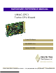


UMAC-CPCI Turbo CPU Board Hardware Reference Manual
Table of Contents
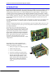
INTRODUCTION.......................................................................................................................................................1
Associated Manuals...................................................................................................................................................2
BOARD CONFIGURATION.....................................................................................................................................3
Option 1: Communications Interfaces.......................................................................................................................3
Option 2: Dual-Ported RAM.....................................................................................................................................3
Option 5: CPU and Memory Configurations.............................................................................................................3
Option 8: High-Accuracy Clock Crystal...................................................................................................................4
Option 9: Serial Port Configuration ..........................................................................................................................4
Option 10: Firmware Revision Specification ............................................................................................................4
Option 16: Battery-Backed Parameter Memory........................................................................................................4
HARDWARE SETUP.................................................................................................................................................5
Clock-Source Jumpers...............................................................................................................................................5
Watchdog Timer Jumper...........................................................................................................................................5
Operation Mode Jumpers ..........................................................................................................................................5
Firmware Reload Jumper ..........................................................................................................................................5
Re-Initialization Jumper............................................................................................................................................5
Serial-Port Level Select Jumpers...............................................................................................................................6
DPRAM IC Select Jumper ........................................................................................................................................6
Flash IC Firmware Bank Select Jumpers ..................................................................................................................6
Flash IC Power Supply Select Jumper ......................................................................................................................6
Power-Supply Check Select Jumper .........................................................................................................................6
Reset-Lock Jumper....................................................................................................................................................6
CONNECTIONS .........................................................................................................................................................7
Compact UBUS Connector .......................................................................................................................................7
Rear Field Wiring Connector ....................................................................................................................................7
Front-Panel RS-232 Connector .................................................................................................................................7
Stack Connectors to Bridge Board ............................................................................................................................7
Factory-Use Connectors............................................................................................................................................8
BOARD LAYOUT.......................................................................................................................................................9
JUMPER DESCRIPTIONS......................................................................................................................................11
E0: Reset-Lock Enable (Factory Use Only)............................................................................................................11
E1A: Servo and Phase Clock Direction Control......................................................................................................11
E1B: Servo/Phase Clock Source Control ................................................................................................................11
E2: (Reserved for Future Use).................................................................................................................................11
E3: Re-Initialization on Reset Control ....................................................................................................................12
E4: (Reserved for Future Use).................................................................................................................................12
E5: USB/Ethernet Communication Jumper.............................................................................................................12
E11: Power Supply Check Control..........................................................................................................................12
E17 – E18: Serial Port Select ..................................................................................................................................12
E18A, B, C, D: Ethernet Communication Control ..................................................................................................13
E19: Watchdog Disable Jumper..............................................................................................................................13
E20 – E22: Power-Up/Reset Load Source ..............................................................................................................13
E23: Firmware Reload Enable.................................................................................................................................13
E25A, B, C: Flash Memory Firmware Bank Select ................................................................................................13
W1: Flash IC Power Supply Select Jumper.............................................................................................................14
CONNECTOR SUMMARY.....................................................................................................................................15
CONNECTOR PINOUTS.........................................................................................................................................17
Compact UBUS Connector (J1) Pin-Out.................................................................................................................17