
Reference Manual


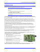


16-Axis MACRO CPU Hardware Reference Manual
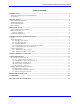
Table of Contents i
Table of Contents
INTRODUCTION .....................................................................................................................................................1
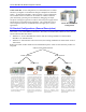
3U Product Configurations (General Description)..................................................................................................2
Configuration ..........................................................................................................................................................3
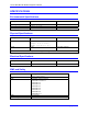
SPECIFICATIONS ...................................................................................................................................................4
Environmental Specifications..................................................................................................................................4
Physical Specifications............................................................................................................................................4
Electrical Specifications..........................................................................................................................................4
EMC and Safety ......................................................................................................................................................4
HARDWARE SETUP ...............................................................................................................................................5
Board Jumper and Switch Summary .......................................................................................................................5
Board Connections ..................................................................................................................................................6
Connector Summary ...........................................................................................................................................6
Hardware Re-initialization ......................................................................................................................................7
JUMPER AND SWITCH CONFIGURATIONS ...................................................................................................9
Layout .....................................................................................................................................................................9
Jumper Descriptions................................................................................................................................................9
E1: Watchdog Timer Disable ............................................................................................................................9
E2: CPU Mode Operation .................................................................................................................................9
E3: Serial Port Baud Rate .................................................................................................................................9
E4: Power Supply-Loss Control (±15Vdc Supply Monitor) ..............................................................................9
E40: MACRO Input (Fiber/Wired) Selector ......................................................................................................9
Switch Configurations...........................................................................................................................................10
SW1: MACRO Slave Node Configure..............................................................................................................10
SW2: MACRO IC 0 Master Number Select .....................................................................................................10
CHARACTER DISPLAY AND LEDS..................................................................................................................11
CONNECTOR PINOUTS ......................................................................................................................................13
Main Board Connectors (603719).........................................................................................................................13
J14, J17: MACRO Copper I/O (OPT C)...........................................................................................................13
U73: MACRO Fiber Optic Connector (OPT A) ...............................................................................................13
TB1: (JPWR) 4-Pin Terminal Block .................................................................................................................14
TB2: (JWD) 4-Pin Terminal Block ...................................................................................................................14
P1: UBUS Interface Connector ........................................................................................................................15
Daughter Board Connections (603720).................................................................................................................16
J2 (JDISP) Display Connector .........................................................................................................................16
J3 (JHW) Handwheel Encoder Connector .......................................................................................................16
J4: (JRS232) Serial Port Connector ................................................................................................................17
HARDWARE MEMORY MAP.............................................................................................................................19
ACCESSORIES.......................................................................................................................................................21
DECLARATION OF CONFORMITY .................................................................................................................23