
Specifications


Chapter 2 Dimensions and Profile
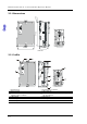
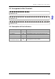
2.3 Arrangement of the Terminals
DVP201 LC-SL
SEN-SEN+SIG-SIG+EXC-EXC+ SHD
DVP202 LC-SL
SEN-SEN+SIG-SIG+EXC-EXC+ SHD SEN-SEN+SIG-SIG+EXC-EXC+ SHD
DVP211LC-SL
SEN-SEN+SIG-SIG+EXC-EXC+
X1X0S/S
SHD
Y1Y0ZPUP
AO+ AO-
Y2 Y3
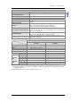
2.4 Description of the Indicators
Name Color Function
POWER indicator Green Displaying power
RUN indicator Green Displaying the status of the module
ERROR indicator Red Displaying an error
L.V indicator Red Showing that the voltage of the an external power is low
LOOP indicator Green Loop control
Motion indicator Orange Showing that measurement is stable
X0 indicator/X1 indicator Red Showing that X0/X1 is On/Off
Y0 indicator/Y1 indicator/
Y2 indicator/Y3 indicator
Red Showing that Y0/Y1/Y2/Y3 is On/Off
2-3