1365 (Model 31-695) PART NO. 902122 - 02-20-04 Copyright © 2004 Delta Machinery To learn more about DELTA MACHINERY visit our website at: www.deltamachinery.com. For Parts, Service, Warranty or other Assistance, please call ESPAÑOL: PÁGINA 21 RTD10000116AA 1-800-223-7278 (In Canada call 1-800-463-3582).
SAFETY GUIDELINES - DEFINITIONS This manual contains information that is important for you to know and understand. This information relates to protecting YOUR SAFETY and PREVENTING EQUIPMENT PROBLEMS. To help you recognize this information, we use the symbols below. Please read the manual and pay attention to these sections. Indicates an imminently hazardous situation which, if not avoided, will result in death or serious injury.
GENERAL SAFETY RULES FAILURE TO FOLLOW THESE RULES MAY RESULT IN SERIOUS INJURY. 12. USE THE RIGHT MACHINE. Don’t force a machine or an attachment to do a job for which it was not designed. Damage to the machine and/or injury may result. 13. USE RECOMMENDED ACCESSORIES. The use of accessories and attachments not recommended by Delta may cause damage to the machine or injury to the user. 14. USE THE PROPER EXTENSION CORD. Make sure your extension cord is in good condition.
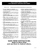
ADDITIONAL SAFETY RULES FOR ABRASIVE FINISHING MACHINES FAILURE TO FOLLOW THESE RULES MAY RESULT IN SERIOUS INJURY. 12. MAINTAIN A MAXIMUM CLEARANCE OF 1/16" between the table and the abrasive disc. The workpiece could be drawn into the space between the abrasive disc and the table. 13. SUPPORT THE WORKPIECE firmly with a miter gauge, backstop, or work table when sanding with a belt. Hold the workpiece firmly. Loss of control of the workpiece can result in injury. 14.
POWER CONNECTIONS A separate electrical circuit should be used for your machines. This circuit should not be less than #12 wire and should be protected with a 20 Amp time lag fuse. If an extension cord is used, use only 3-wire extension cords which have 3prong grounding type plugs and matching receptacle which will accept the machine’s plug.
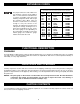
EXTENSION CORDS MINIMUM GAUGE EXTENSION CORD RECOMMENDED SIZES FOR USE WITH STATIONARY ELECTRIC MACHINES Use proper extension cords. Make sure your extension cord is in good condition and is a 3-wire extension cord which has a 3-prong grounding type plug and matching receptacle which will accept the machine’s plug. When using an extension cord, be sure to use one heavy enough to carry the current of the machine.
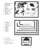
1 1. 2. 3. 4. 5. 6. 7. 8. 9. 10. 11. 12. 13. 14. Sander with 6" x 48" Sanding Belt and Backstop Sanding Disc Plate Belt and Pulley Cover 9" Sanding Disc Plug T-Wrench Drive Belt M6 x 55mm Hex Socket Head Screws (2) M6.4 Flat Washer (2 M6.4 Lockwasher (2) Disc Cover M4.2 x 13mm Panhead Screws (3) Support Rod Table Assembly 3 2 4 14 11 5 8 10 12 9 6 13 7 Fig.
ASSEMBLY For your own safety, do not connect the machine to the power source until the machine is completely assembled and you read and understand the entire instruction manual. STAND IMPORTANT: Any letter designations that are stamped on the braces of the stand are for production purposes ONLY and are not used for assembling the stand. Follow the instructions in this manual. A B Assembling this stand (Fig.
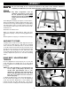
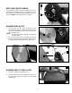
A BELT AND PULLEY GUARD C Place an M6.4 lockwasher and an M6.4 flat washer in that order on two M6 x 55mm hex socket head screws (B), and attach the belt and pulley guard (A) Fig. 8 to the machine. NOTE: Install the plug (C) in the guard. B Fig. 8 SANDING DISC PLATE C 1. Place the key (C) Fig. 9 into the keyway of the driveshaft and slide the sanding disc plate (A) Fig. 9 on the drive shaft until it is flush with the end of the drive shaft (Fig. 10).
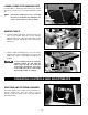
LOWER COVER FOR SANDING DISC C Use three M4.2 x 13mm pan head screws (C) to attach the lower cover (A) Fig. 13 to the belt and pulley guard (B). NOTE: B A Prevent the sanding disc from contacting the lower cover. Rotate the sanding disc by hand to ensure that no contact is made. Fig. 13 B C SANDER TABLE 5-1/2" 1. Insert the support rod (A) Fig. 14 into the hole in the side of the sander until the rod (A) extends approximately 5-1/2". Align the flat on the rod (A) with the screw (B).
B A Fig. 18 Fig. 17 LOCKING SWITCH IN THE “OFF” POSITION When the machine is not in use, the switch should be locked in the “OFF” position to prevent unauthorized use. This can be done by grasping the switch toggle (B) and pulling it out of the switch, as shown in Fig. 20. With the switch toggle (B) removed, the switch will not operate. However, should the switch toggle be removed while the sander is running, it can be turned “OFF” once, but cannot be restarted without inserting the switch toggle (B).
2. Place a level (A) on the sanding belt. B A 3. To adjust, loosen the lock nut (B) Fig. 21, and turn the sanding arm stop (C) in or out until the sanding arm is level. After adjustment, tighten the lock nut (B). C Fig. 21 A ADJUSTING BACKSTOP SQUARE WITH SANDING BELT DISCONNECT MACHINE FROM POWER SOURCE. 1. Before making this adjustment, check to see that the belt tension lever (A) Fig. 22 is all the way to the left in the “tighten” position. 2. Place a square (B) Fig.
SQUARING TABLE WITH SANDING DISC C DISCONNECT MACHINE FROM POWER SOURCE. 1. Place one end of a combination square (C) Fig. 25 on the table with the other end against the sanding disc. B 2. If the table surface is not 90 degrees to the disc, loosen the table lock knob (A) Fig. 25, adjust the table, and tighten lock knob (A). A 3. Adjust the pointer (B) Fig. 25 to the “0” degree mark on the angle scale. Fig.
A USING TABLE ASSEMBLY WITH SANDING BELT C D Use the table assembly with the sanding belt in the vertical position ONLY. To move the table assembly (B) Fig. 30 to the sanding arm (A): 1. Remove the backstop (C) Fig. 30. 2. Loosen the screw (D) Fig. 30 and carefully remove support bar (E) and table assembly (B) from the disc unit. G B D Fig. 30 3. Loosen the set screw (F) Fig. 31. insert the support bar (E) (with the table assembly (B) attached) in the hole (G) Figs. 30 & 31. Tighten the set screw (F).
2. If you are sanding with the belt, pull the dust shield (A) Fig. 34 outward. A Fig. 34 A WRENCH STORAGE A hole is provided in the stand for storing the hex wrench (A) Fig. 35, supplied with the sander. REMOVING UPPER SANDING DRUM GUARD Fig. 35 A B You can remove the upper sanding drum guard (A) Fig. 36 to sand inside curved work or to change the belt. To remove: 1. Pull outward on the guard (A). 2. After the sanding operation is completed or the belt is changed, replace the guard (A) Fig.
F 4. Move the tension lever (E) Fig. 39, to the right to the “LOOSEN” position (F). Remove the sanding belt (F) from both sanding drums. E 5. Place a new 6" x 48" sanding belt (F) Fig. 40 over both sanding drums (G). Ensure that the belt will travel in the direction of the arrows printed on the inside of the belt. Fig. 39 6. Move the tension lever (E) Fig. 39 left to the “TIGHTEN” position. F G 7. Replace the support bracket, backstop and upper sanding drum guard, removed in STEPS 1 and 2. G 8.
OPERATING CONTROLS AND ADJUSTMENTS A A Fig. 44 Fig. 45 SURFACING OR EDGE SANDING WITH SANDING BELT When surfacing (Fig. 44) or edge sanding (Fig. 45), place the sanding arm in the horizontal position and use the backstop (A) Fig. 44 and Fig. 45 to keep the workpiece in place. Hold the workpiece firmly and keep your fingers away from the sanding belt. Place the end of the workpiece against the backstop and move the workpiece evenly across the sanding belt.
Fig. 49 Fig. 48 END SANDING WITH THE DISC When sanding the ends of narrow workpieces, use the sanding disc and the accessory miter gauge (Fig. 48). Move the work from the center to the left side of the sanding disc. Always sand on the left (downward) side of the sanding disc. Sanding on the right (upward) side of the sanding disc could cause the workpiece to fly up, which could be hazardous.
MAINTENANCE KEEP MACHINE CLEAN PROTECTING CAST IRON FROM RUST Periodically blow out all air passages with dry compressed air. All plastic parts should be cleaned with a soft damp cloth. NEVER use solvents to clean plastic parts. They could possibly dissolve or otherwise damage the material.
ACCESSORIES A complete line of accessories is available from your Delta Supplier, Porter-Cable • Delta Factory Service Centers, and Delta Authorized Service Stations. Please visit our Web Site www.deltamachinery.com for a catalog or for the name of your nearest supplier. Since accessories other than those offered by Delta have not been tested with this product, use of such accessories could be hazardous. For safest operation, only Delta recommended accessories should be used with this product.
PORTER-CABLE • DELTA SERVICE CENTERS (CENTROS DE SERVICIO DE PORTER-CABLE • DELTA) Parts and Repair Service for Porter-Cable • Delta Machinery are Available at These Locations (Obtenga Refaccion de Partes o Servicio para su Herramienta en los Siguientes Centros de Porter-Cable • Delta) ARIZONA Tempe 85282 (Phoenix) 2400 West Southern Avenue Suite 105 Phone: (602) 437-1200 Fax: (602) 437-2200 CALIFORNIA Ontario 91761 (Los Angeles) 3949A East Guasti Road Phone: (909) 390-5555 Fax: (909) 390-5554 Tampa 3360