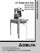
(Model 33-890) (Model 33-891) (Model 33-892) PART NO. 424-02-651-0023 (018) Copyright © 2001 Delta Machinery To learn more about DELTA MACHINERY visit our website at: www.deltamachinery.com. For Parts, Service, Warranty or other Assistance, please call 1-800-223-7278 (In Canada call 1-800-463-3582).
GENERAL SAFETY RULES Woodworking can be dangerous if safe and proper operating procedures are not followed. As with all machinery, there are certain hazards involved with the operation of the product. Using the machine with respect and caution will considerably lessen the possibility of personal injury. However, if normal safety precautions are overlooked or ignored, personal injury to the operator may result.
ADDITIONAL SAFETY RULES FOR RADIAL ARM SAWS WARNING: FAILURE TO FOLLOW THESE RULES MAY RESULT IN SERIOUS PERSONAL INJURY 1. IF YOU ARE NOT thoroughly familiar with the operation for Radial Saws, obtain advice from your supervisor, instructor, or other qualified person. 2. MAKE SURE wiring codes and recommended electrical connections are followed and that machine is properly grounded. 3. KEEP saw blade sharp and free of all rust and pitch. 4. KEEP blade and arbor flanges free from dirt and grease. 5.
POWER CONNECTIONS A separate electrical circuit should be used for your tools. This circuit should not be less than #12 wire and should be protected with a 20 Amp time lag fuse. If an extension cord is used, use only 3-wire extension cords which have 3prong grounding type plugs and matching receptacle which will accept the tool’s plug.
EXTENSION CORDS Use proper extension cords. Make sure your extension cord is in good condition and is a 3-wire extension cord which has a 3-prong grounding type plug and matching receptacle which will accept the tool’s plug. When using an extension cord, be sure to use one heavy enough to carry the current of the tool. An undersized cord will cause a drop in line voltage, resulting in loss of power and overheating. Fig. D, shows the correct gauge to use depending on the cord length.
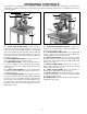
OPERATING CONTROLS The following is an explanation of the operating controls of the Delta 10” Radial Saw. We suggest you study these explanations carefully to familiarize yourself with the controls before turning on the power, to avoid damage to the saw or personal injury. A M L C B G D J E F H K Fig. 2 Fig. 3 A – TRACK ARM CLAMP KNOB. Controls swing of track arm for all miter cutting operations. Locks track arm at any angle for the full 360º rotation.
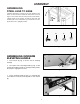
ASSEMBLY ASSEMBLING STEEL LEGS TO BASE Carefully support the machine to the rear and brace the frame so the machine is balanced. Attach the four steel legs to each end of the base using sixteen 5/16-18x5/8" carriage head screws (A) Fig. 4A and Fig. 4B, 5/16" flat washers (B), 5/16" lockwashers (C) and 5/16" hex nuts (D). Return saw to upright position. A D B C Fig. 4A A D B C Fig. 4B ASSEMBLING OVERARM ELEVATING HANDLE C 1. Insert roll pin (A) Fig. 5, into the hole in elevating shaft (B). 2.
ASSEMBLING CUTTINGHEAD TO TRACK ARM C F E D 1. Raise the track arm assembly (A) Fig. 7, by turning overarm elevating handle (F) Fig. 2. A 2. Remove packing material from around cuttinghead assembly (B) Fig. 7. B 3. Push track arm clamp lever (C) Fig. 7, to the rear until it rests against stop (D) as shown. Fig. 7 4. Pull out on track arm index knob (E) Fig. 7, and rotate track arm (F) 90 degrees to the position shown in Fig. 8. Tighten track arm clamp lever (C) Fig. 8, by pulling it to front position.
8. Assemble end cap (N) Fig. 12, to the rear of track arm assembly (A) and fasten with two 5/16-18x3/4" button head screws (P) and 5/16" lockwashers (Q) supplied. Q A N P Fig. 12 ASSEMBLING STARTER BOX TO BASE If you purchased your machine with magnetic starter, transformer and overload protection, assemble the starter box to the base, as follows: 1. Assemble bracket (A) to the bottom of the right side of saw base, as shown in Fig. 13.
B A C ADJUSTING TABLE BRACKETS PARALLEL TO TRACK ARM Fig. 16 To perform accurate work, the track arm must be parallel to the table top brackets at both the front and rear of the machine. To check if the alignment is correct, proceed as follows: 1. Loosen yoke clamp locking lever (A) Fig. 16, pull up yoke clamp index knob (B) and rotate yoke (C) to the out rip position shown in Fig. 17. Tighten yoke clamp locking lever (A). B A C Fig. 17 2. Place wrench (D) Fig.
3. Place wrench (F) Fig. 19, between inner flange (G), and outer flange (H) and tighten arbor nut (E). Make certain wrench (F) is above the table surface. If necessary raise track arm. G E H F Fig. 19 L 4. Loosen cuttinghead clamp knob (J) Fig. 20 and move cuttinghead (C) to the front of track arm (K). Loosen track arm locking lever (L), pull out on track arm index knob (M) and rotate track arm (K) until wrench (F) is over left table bracket (N).
R N T 7. If an adjustment is necessary, remove screw (R) Fig. 23, loosen locknut (S) and turn leveling screw (T) to raise or lower table mounting bracket (N). When adjustment is complete, tighten locknut (S) and replace screw (R). S Fig. 23 8. Check and adjust the other table mounting bracket in the same manner. IMPORTANT: Do not raise or lower the track arm assembly while checking or making the adjustments. N 9. Place a straight edge (V) Fig.
ASSEMBLING TABLE BOARDS A 1. Place main table board (A) Fig. 27, on the table mounting brackets making sure that the two roll pins in the table mounting brackets fit into the two holes in bottom of main table board (A). Fasten table in place, place a 1/4" flat washer onto a 1/4-20x1-3/4" round head screw and insert the screws through holes (B) predrilled in the main table board (A) and tighten securely. B B Fig. 27 C D 2. Place the remaining loose boards (C) Fig.
5. Remove screw, flat washer and spacer (G) Fig. 31, that fasten the front inside leaf guard (H) to front end of blade guard (J). Assemble blade guard (J) to motor assembly with locking rod (K). K J 6. Reassemble leaf guard (H) Fig. 31, to blade guard (J) using screw, flat washer and spacer (G). G H Fig. 31 7. Fig. 32, illustrates the blade guard assembly attached to the motor assembly. Fig.
OPERATING CONTROLS AND ADJUSTMENTS Every Delta Radial Saw is thoroughly tested, inspected and accurately aligned before leaving the factory, and when delivered is ready for operation after it is assembled. However, regardless of the care with which this or any piece of fine machinery is manufactured, inspected and shipped, it is possible that rough handling in shipment may make minor adjustments necessary. CAUTION: ALWAYS DISCONNECT SAW FROM POWER SOURCE BEFORE MAKING ANY ADJUSTMENTS.
ADJUSTING CUTTINGHEAD BALL BEARINGS AGAINST TRACK RODS The carriage is mounted on four pre-loaded, prelubricated, shielded ball bearings: two on fixed shafts (on saw blade side of track arm); the other two on adjustable eccentric shafts. C The ball bearings must ride smoothly and evenly against the track rods to do accurate work. If wear should ever develop in the track rods causing “play” between the ball bearings and the track rods, the ball bearings can be adjusted as follows: A B 1.
ADJUSTING BLADE SQUARE WITH TABLE TOP A The saw blade must be square with the table top in order to produce accurate work. To check if the blade is square with the table: B 1. DISCONNECT TOOL FROM POWER SOURCE. 2. Remove the blade guard and place the cuttinghead in a cross-cut position as shown in Fig. 42. 3. Place a steel square (A) Fig. 42, against saw blade (B) and table, and check to see if the blade (B) is square with the table. Make certain the square is between the teeth of the saw blade. Fig.
7. When the adjustment is made, turn the bevel clamp handle (F) Fig. 46, counterclockwise to lock the motor in position. NOTE: If the bevel clamp handle (F) does not completely lock the motor, the clamp handle can be repositioned by pulling out the handle and repositioning it on the serrated nut located under the handle. F Fig. 46 8. Tighten bolt (D) Fig. 44, and two bolts (C) Fig. 43. 9. Loosen screw (G) Fig. 47. Move pointer (H) to zero mark on the bevel scale (J). Tighten screw (G). J 10.
A ADJUSTING SAW TRAVEL SQUARE WITH FENCE B The 12” Radial Arm Saw is equipped with 90 degree and 45 degree positive miter stops. This feature makes it possible to produce accurate miter cuts and square cross-cuts at all times. C To do accurate work, the saw blade travel must be 90 degrees to the fence. If saw blade travel is not 90 degrees to the fence, this means that the track arm is not properly aligned. Fig. 50 E D To check and adjust, proceed as follows: 1. DISCONNECT TOOL FROM POWER SOURCE. 2.
REMOVING “HEELING” IN SAW CUT Even though the cuttinghead travel may be perfectly aligned at 90 degrees to the fence, the blade itself may not be 90 degrees or square with the fence, as shown in Fig. 54. This condition is known as “heeling.” To check and adjust, proceed as follows: 1. DISCONNECT TOOL FROM POWER SOURCE. Fig. 54 2. Take a piece of 3/4” plywood or similar piece of wood (A) Fig. 55, at least 5” wide, and clamp it between the table boards in place of the fence, as shown. 3.
ADJUSTING BLADE GUARD AND ANTI-KICKBACK ROD E C On all ripping and plowing operations, the back part of the blade guard is lowered so that it just clears the material. This will prevent the material from being lifted off the table. Also, lower the kickback rod (A) Fig. 57, so that the kickback fingers (B) are below surface of material. Rod (A) can be raised or lowered by loosening wingnut (C), moving the kickback rod to the desired position and tightening wingnut (C).
ASSEMBLING ACCESSORY 33-967 MOULDING CUTTERHEAD GUARD To assemble the accessory 33-967 Moulding Cutterhead Guard to your Radial Arm Saw, proceed as follows: 1. DISCONNECT TOOL FROM POWER SOURCE. 2. Remove blade, and blade guard assembly. B A 3. Move motor so that the arbor is in the down position, as shown in Fig. 60. Fig. 60 4. Place guard (A) Fig. 60, on motor with stud on motor inserted through hole in guard. Thread special nut (B) on motor stud and fasten with screwdriver, as shown in Fig. 60.
MITER CUTTING B Miter cutting is similar to cross-cutting except the workpiece is cut off at an angle (up to 45 degrees right or left) rather than being cut off square. The settings and operation are performed in the same manner as crosscutting except that the track arm (A) Fig. 63, is first positioned to the desired angle on the miter scale before it is clamped in place with clamp handle (B).
IN-RIPPING In-ripping involves all of the general conditions stated under RIPPING. The yoke is clamped at right angle to the track arm with the blade guard facing the rear of the machine. The cuttinghead is positioned on the in-rip scale to the desired setting and clamped in position. The workpiece is fed from the right side of the saw. Fig. 66, shows a typical in-ripping operation on the radial saw. Note the push stick is being used due to the narrow workpiece. B C Fig.
CONSTRUCTING A PUSH STICK 25 1/2" SQUARES CUT OFF HERE TO PUSH 1/2" WOOD CUT OFF HERE TO PUSH 1/4" WOOD NOTCH TO HELP PREVENT HAND FROM SLIPPING MAKE FROM 1/2" OR 3/4" WOOD OR THICKNESS LESS THAN WIDTH OF MAT’L. TO BE CUT PUSH STICK When ripping work less than 4 inches wide, a push stick should be used to complete the feed and could easily be made from scrap material by following the pattern shown.
NOTES 26
ACCESSORIES A complete line of accessories is available from your Delta Supplier, Porter-Cable • Delta Factory Service Centers, and Delta Authorized Service Stations. Please visit our Web Site www.deltamachinery.com for a catalog or for the name of your nearest supplier. WARNING: Since accessories other than those offered by Delta have not been tested with this product, use of such accessories could be hazardous. For safest operation, only Delta recommended accessories should be used with this product.
PORTER-CABLE • DELTA SERVICE CENTERS (CENTROS DE SERVICIO DE PORTER-CABLE • DELTA) Parts and Repair Service for Porter-Cable • Delta Power Tools are Available at These Locations (Obtenga Refaccion de Partes o Servicio para su Herramienta en los Siguientes Centros de Porter-Cable • Delta) ARIZONA Tempe 85282 (Phoenix) 2400 West Southern Avenue Suite 105 Phone: (602) 437-1200 Fax: (602) 437-2200 CALIFORNIA Ontario 91761 (Los Angeles) 3949A East Guasti Road Phone: (909) 390-5555 Fax: (909) 390-5554 San Lean