(Model 36-842) 36-842 Consists of: 36-869 Base Unit 36-937 10" Cast Iron Wings (2) 36-918 (52") Unifence Assembly 36-947 Gray table boards 36-904 Unifence front rail with stop 35-617 Carbide blade 50-289 Mobile Base 36-862 Zero Clearance Insert Limited Edition 3 H.P.
GENERAL SAFETY RULES Woodworking can be dangerous if safe and proper operating procedures are not followed. As with all machinery, there are certain hazards involved with the operation of the product. Using the machine with respect and caution will considerably lessen the possibility of personal injury. However, if normal safety precautions are overlooked or ignored, personal injury to the operator may result.
ADDITIONAL SAFETY RULES FOR TABLE SAWS WARNING: FAILURE TO FOLLOW THESE RULES MAY RESULT IN SERIOUS PERSONAL INJURY. 10. NEVER run the workpiece between the fence and a moulding cutterhead. 1. DO NOT OPERATE THIS MACHINE until it is assembled and installed according to the instructions. 11. NEVER perform “free-hand” operations. Use either the fence or miter gauge to position and guide the workpiece. 2.
POWER CONNECTIONS A separate electrical circuit should be used for your machines. This circuit should not be less than #12 wire and should be protected with a 20 Amp time lag fuse. If an extension cord is used, use only 3-wire extension cords which have 3prong grounding type plugs and matching receptacle which will accept the machine’s plug.
EXTENSION CORDS Use proper extension cords. Make sure your extension cord is in good condition and is a 3-wire extension cord which has a 3-prong grounding type plug and matching receptacle which will accept the machine’s plug. When using an extension cord, be sure to use one heavy enough to carry the current of the machine. An undersized cord will cause a drop in line voltage, resulting in loss of power and overheating. Fig. D, shows the correct gauge to use depending on the cord length.
UNISAW 1. 2. 3. 4. 5. 6. 7. 8. 9. 10. 11. 12. 13. 14. 15. 16. 17. 18. 19. 20. 21. 22. 23. 24. 25. 26. 27. 28. 29. 30. 31. 32. 33. Unisaw Switch Motor cover Blade guard and splitter bracket Support rod 5/8" Internal tooth washer 5/8-18 Jam nut Upper bracket for splitter Lower bracket for support rod 5/16" l.D. Flat washers (2) 5/16" l.D.
52" UNIFENCE 1. 2. 3. 4. 5. 6. 7. 8. 9. 10. 11. 12. 13. 14. 15. Unifence body (1) Fence (1) Shelf support bracket (2) Legs (2) Table support brackets (2) Unifence cursor (1) Unifence guide rail (1) #8 x 7/8" wood screws (17) Z brackets (3) 16. 17. 18. 19.
50" COMMERCIAL BIESEMEYER FENCE SYSTEM & OUTFEED TABLE 1 3 2 17 5 18 10 15 16 6 8 8 9 7 11 12 13 Fig. 4 9 14 24 4 25 27 28 26 19 21 20 29 22 23 30 Fig. 5 33 32 31 Fig. 6 NOTE: A common hardware package is used for several different models, therefore you may have leftover hardware. Fig. 4 1 - Rear Rail 2 - Front Rail 3 - Guide Tube 4 - T-Square® Fence Assembly (Fig. 5) 5 - Cable Strap 6 - Template for aligning front rail to saw table for fastening guide tube to front rail Fig.
LIMITED EDITION UNISAW ASSEMBLY INSTRUCTIONS WARNING: FOR YOUR OWN SAFETY, DO NOT CONNECT THE SAW TO THE POWER SOURCE UNTIL THE SAW IS COMPLETELY ASSEMBLED AND YOU READ AND UNDERSTAND THE ENTIRE INSTRUCTION MANUAL. ASSEMBLING BLADE TILTING MECHANISM HANDLE D A 1. Install fiber washer (A) Fig. 6A, on the blade tilting mechanism shaft (B). Install key (C), into shaft keyway. B 2. Place handwheel (D) on shaft (B) Fig. 6A. Make sure the groove (E), in the handwheel lines up with the key (C). C 3.
F E A D D G C Fig. 11 Fig. 12 ASSEMBLING ON/OFF SWITCH B 1. Loosely assemble switch and switch bracket (A) Fig. 12, to the inside front lip of the left extension wing with 5/16-18x1" hex flat head screw (D), 5/16" flat washer (E), and 5/16-18 hex nut (F) through hole (G) Fig. 11. 2. Attach the side of switch bracket (A) Fig. 12, to the inside of extension wing at the front of the saw using the 7/16"-20x 11/4" screw and 7/16" lockwasher. 3. Tighten screws (C) and (D), Fig. 12, securely. A Fig.
H J G Fig. 16 Fig. 17 6. Insert threaded end of support rod (G) Fig. 16, through slot in back of saw and through hole (H) Fig. 16, in rear trunnion. Fasten support rod (G) Fig. 16, to trunnion using star washer and 5/8-18 nut (J) Fig. 17. NOTE: Thread nut (J) onto threaded end of support rod as far as possible by hand. Using a wrench to hold nut (J) Fig. 17, tighten rod (G) Fig. 18, using a small screwdriver (K) or similar device through hole in end of rod (G) as shown. G K Fig. 18 7.
10. Assemble splitter (P) Fig. 22, inside the splitter mounting bracket as shown. Push splitter (P) down as far as possible, making certain bottom edge (T) of splitter (P) is parallel with table surface, and tighten screw (B). T U P 11. Reassemble the saw blade (U) Fig. 22. 12. Using a straight edge (A) Fig. 23, and square (B) Fig. 24, align splitter (P) with the saw blade and table by moving brackets (M) and (L) until the splitter (P) is in perfect alignment with the blade and square with the table.
MOTOR COVER Removing the motor cover To remove the motor cover, push motor cover to one side to depress clips, and rotate motor cover away from the cabinet. Attaching the motor cover A Place the motor cover (A) in the opening of the Unisaw as shown in Fig. 31. Place the rear motor cover clips inside the motor opening and push the front of the motor cover until all 4 motor cover clips are engaged with the motor cover opening in the Unisaw. Fig. 31 Fig. 32 shows the motor cover attached to the Unisaw.
ASSEMBLING DUST CHUTE ADAPTER A The Unisaw is supplied with a dust chute connector to provide a means of connecting a dust collector to the machine. Align the four holes in the dust chute adapter (A) Fig. 34A,with the four holes in the back of the saw cabinet (B) and attach the dust chute adapter with four #10 x 1/2" sheet metal screws. B Fig. 34A ASSEMBLY INSTRUCTIONS FOR MODEL 36-842 52" UNIFENCE ASSEMBLING UNIFENCE TABLE AND SHELF BOARD 1. Fig.
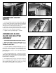
A A A C B Fig. 37 Fig. 38 3. Assemble the two table legs (A) Fig. 37 to the bottom of the table using eight #8x7/8" wood screws. 4. Assemble shelf support bracket (B) Figs. 38 & 51, to the table legs (A) using two U-clamps (C), 1/4" flat washers, and 1/4-20 hex nuts. NOTE: Height adjustments to the bracket will be made later. 5. Insert foot adapter (T) Fig. 39, into the bottom of each leg (A), using a rubber mallet. Assemble the 3/8" jam nut (V) approximately 3/4 of the way onto leveling screw (W).
L M J K J Fig. 42 Fig. 43 7. Assemble Z-brackets (J) Fig. 42, to the inside edge on right side of extension wing (K) as shown, using three 7/16-20x 3/4" hex head screws, lockwashers, and flat washers (L). Place lockwasher, washer, z-bracket onto screw and thread screw from the inside of the extension wing and tighten securely. NOTE: Using a square (M) Fig. 43, make certain that Z-brackets (J) are perpendicular to the saw table as shown.
N R S K Fig. 47 Fig. 48 11. Position table board (R) Fig. 47, on top of angle brackets (N) as shown. Q 12. While holding table board (R) Fig. 47, tightly against extension wing (K), fasten table (R) to brackets (N) Fig. 47, from underneath the table using three #8 x 7/8 inch-long wood screws (Q) Fig. 49. CAUTION: DO NOT OVERTIGHTEN TABLE MOUNTING SCREWS. NOTE: Pilot holes can be drilled in the particle board using a 1/16" drill bit, drilling a 1/2" deep, to help attaching the table brackets.
ASSEMBLING UNIFENCE GUIDE RAIL TO TABLE C 1. Locate the Guide Rail and mounting hardware from the packing material of the Unifence. 2. The guide rail has end caps inserted into each end of the rail. Remove the end cap (B) Fig. 52, by inserting a flathead screwdriver (C) into the channel in the guide rail and press outward against the inside of the end cap (B) as shown. The end cap (B) will pop out.
A C 7. Adjust the guide rail parallel with the saw table surface by placing a square on the saw table at both the left and right front ends of the table. The guide rail can be adjusted up or down at either end. After you are certain the guide rail is parallel with the table surface, firmly tighten the two hex nuts that fasten the guide rail to the table. Fig. 56 8. Move the square (H) Fig.
P F R G Fig. 62 Fig. 61 SETTING FLIP STOP 1. The Flip Stop Assembly Fig. 62, can be set to any number of positions along the guide rail providing a quick stop setting for the Unifence body by loosening knob (G) and sliding the stop along the rail to the desired position and re- tighten. 2. Any number of stops, Delta Cat. No. 36-899, can be purchased and installed to provide time saving quick stop settings for the Unifence body. 3. If flip stop does not retract fully the bolt (F) Fig.
ASSEMBLING UNIFENCE BODY TO GUIDE RAIL C E F B 1. Turn fence body (A) Fig. 66, upside down and lay it on a table or bench. Pull handle (B) out against fence body. Make certain the surface (C) of clamp bracket is parallel to the face (D) of the fence body, and that the inside edge (E) of the clamp bracket is parallel to surface (F) of the fence body. Turn handle (B) Fig. 66, if necessary. A D Fig. 66 2. Place fence body (A) Fig.
C C A A B B Fig. 71 Fig. 70 ASSEMBLING FENCE TO UNIFENCE BODY 1. The fence (A) can be assembled to clamp plate (B) in either the horizontal position as shown in Fig. 70, or the vertical position as shown in Fig. 71. Make certain the two lock knobs, one of which is shown at (C), are loose and slide fence (A) onto clamp plate (B) as shown. Then tighten the two lock knobs (C). 2. For most normal ripping operations, the bottom of the fence should be positioned slightly above the table surface.
5. The distance the fence is positioned away from the blade is indicated by the two witness lines (B) and (C) Fig. 76, located on the cursor (D). Witness line (B) indicates the distance the fence is away from the blade when the fence is in the horizontal position, and witness line (C) indicates the distance the fence is away from the blade when the fence is in the vertical position.
B A Fig. 80 Fig. 79A When ripping material with a veneer facing that extends over the material, the fence (A) should be in the horizontal position with the veneer (B) extending over the lip of the fence, as shown in Fig. 80. When ripping material with a veneer facing and the material is not thick enough for the veneer to extend over the lip of the fence or if the veneer facing (B) is on both sides of the material, as shown in Fig. 81, the fence can be positioned slightly above the surface of the table.
ADJUSTING CLAMPING ACTION OF FENCE LOCKING HANDLE C C When the fence locking handle (A) is pushed to the down position, as shown in Fig. 84, the fence body (B) should be completely clamped to the guide rail. If the fence body (B) is not completely clamped to the guide rail when the handle (A) is in the position shown in Fig. 84, lift up on locking handle (A) Fig. 85, and slightly tighten two adjustment plugs (C) using the arbor wrench or 7/8" wrench.
B A Fig. 88 Fig. 89 USING THE FENCE AS A CUT-OFF GAGE B WARNING: WHEN USING YOUR UNIFENCE AS A CUT-OFF GAGE, MAKE SURE IT IS PROPERLY SET UP AS DESCRIBED HERE. The fence can be used as a cut-off gage when cross cutting a number of pieces to the same length. IMPORTANT: When using the fence as a cut-off gage, it is very important that the rear end of the fence be positioned so that the work piece is clear of the fence before it contacts the saw blade. Fig.
ASSEMBLY INSTRUCTIONS FOR MODELS 36-844 & 36-845 50" COMMERCIAL BIESEMEYER FENCE ASSEMBLING GUIDE RAILS B 1. Assemble the front rail (A) Fig. 92, to front of saw table using the two 3/8-16 x 1-1/4" long flat head Phillips screws (B), 7/8" flat washers, lockwashers and 3/8-16 hex nuts supplied. Screws (B) are inserted through the two holes in the front rail, as shown and through the two through holes in the front of the saw table and fastened to the table with the flat washers, lockwashers and hex nuts.
ASSEMBLING TABLE LEGS TO EXTENSION TABLE TABLE BOARD HOLE LOCATION FOR SAW WITH MOBILE BASE IMPORTANT: If your saw will be used with a mobile base underneath the saw base and table legs, the position of the legs may have to be changed to fit onto the mobile base, see Fig. 96. Fig. 96 1. Position the two legs (H) Fig. 97, at the two far corners of the inside of one end of the extension table, as shown, and mark the position of the eight holes to be drilled into the bottom of the table.
ASSEMBLING EXTENSION TABLE TO FRONT AND REAR RAILS P N S 1. Place table assembly (N) Fig. 100, in position between the two rails, as shown. Make sure end of table (N) is flush against extension wing (P). Using a straight edge make sure table (N) is in the same plane and level with saw table (P). Lightly tap table up or down and adjust leveling screws (R) Fig. 101, in bottom of legs to accomplish this. When the table (N) Fig.
REAR SUPPORT TABLE MOUNTING INSTRUCTIONS FOR MODEL 36-845 ONLY H I 1. Position the two legs (H) Fig. 104, at the two far corners of the inside of one end of the extension table, as shown, and mark the position of the eight holes to be drilled into the bottom of the table. Remove the two legs (H) and using a 1/16" drill bit, drill the eight holes 1/2" deep. Replace the two legs and fasten to the bottom of the table using the eight 3/4" wood screws (I) supplied.
5. Use a 3/16" drill bit to drill the two holes in the rear rail, approximately 71/2" from each corner of the table board, Fig. 107 & 108 (marked in step 4). Fig. 108 6. After the holes are drilled in the rear rail, position the table board back onto the rear rail,and up against the rear rail, and drill through the holes in the rear rail through the table board, Fig. 109 (shown from underneath the rear guide rail and the table). Fig. 109 7.
FENCE OPERATION IMPORTANT: Before operating fence, make sure the fence is adjusted parallel to the miter gage slot, as explained later on in this manual. 1. To place the fence on the guide rail, lift up clamp (A) Fig. 112, and place the fence over the rail and gently push fence onto rail (B) Fig. 112. 2. To move the fence along the guide rail, lift up clamp lever (A) as shown in Fig. 112, slide fence to desired position on rail, and push down on clamp lever (A) as shown in Fig.
ADJUSTING FENCE PARALLEL TO MITER GAGE SLOTS A B NOTE: Delta table saws have been aligned at the factory so that the miter gage slots in the table are parallel with the saw blade. It is recommended, however, to check and make certain this alignment is correct before adjusting the fence parallel to the miter gage slot as follows: The fence (A) Fig. 116, must be adjusted so it is parallel to the miter gage slots (B).
OPERATING CONTROLS AND UNISAW ADJUSTMENTS STARTING AND STOPPING THE SAW To turn the saw “ON”, push the “ON” button (A) Fig. 119. To stop the machine, push the “OFF” button (B). A LOCKING SWITCH IN THE “OFF” POSITION B IMPORTANT: When the machine is not in use, the switch should be locked in the “OFF” position using a padlock (A) Fig. 120, (Delta Cat. No. 50-325), with a 3/16" diameter shackle to prevent unauthorized use. Fig. 119 OVERLOAD PROTECTION Your saw is supplied with overload protection.
ADJUSTING 90 AND 45 DEGREE POSITIVE STOPS B Positive stops are provided to quickly and accurately position the blade at 90 and 45 degrees to the table. To check and adjust the positive stops, proceed as follows: A 1. DISCONNECT MACHINE FROM POWER SOURCE. 2. Raise the saw blade all the way to the top and turn the blade tilting handwheel clockwise as far as it will go. Fig. 122 3. Using a square, check to see if the blade is 90 degrees to the table.
ADJUSTING TABLE INSERT Place a straight edge (B) across the table at both ends of the table insert as shown in Fig. 126. The table insert (A) should always be level with the table. If an adjustment is necessary, turn the adjusting screws (C), as needed with allen wrench supplied. NOTE: THE MITER GAGE HANDLE CAN BE USED TO STORE THE ALLEN WRENCHES WHEN NOT IN USE. REMOVE THE TOP CAP OF THE MITER GAGE HANDLE FOR THE ALLEN WRENCH STORAGE COMPARTMENT. C A B C Fig.
MAINTENANCE CHANGING THE SAW BLADE 1. DISCONNECT MACHINE FROM POWER SOURCE. B 2. NOTE: Two wrenches are supplied with the saw for changing the saw blade; a box end wrench and open end wrench. 3. Remove table insert and raise saw blade to its maximum height. C A 4. Place the open end wrench (B) Fig. 130, on the flats of the saw arbor to keep the arbor from turning, and using wrench (A), turn the arbor nut (C) clockwise. Remove arbor nut, blade flange and saw blade. Fig.
PROTECTING CAST IRON TABLE FROM RUST To clean and protect cast iron tables from rust, you will need the following materials: 1 pushblock from a jointer, 1 sheet of medium Scotch-Brite™ Blending Hand Pad, 1 can of WD-40®, 1 can of degreaser, 1 can of TopCote® Aerosol. Apply the WD-40 and polish the table surface with the Scotch-Brite pad using the pushblock as a holddown. Degrease the table, then apply the TopCote® accordingly.
RIPPING Ripping is the operation of making a lengthwise cut through a board, as shown in Fig. 136, and the rip fence (A) is used to position and guide the work. One edge of the work rides against the rip fence while the flat side of the board rests on the table. Since the work is pushed along the fence, it must have a straight edge and make solid contact with the table. The saw guard must be used.
IMPORTANT: For certain cutting operations such as dadoing and moulding where you are not cutting completely through the workpiece, the blade guard and splitter assembly cannot be used. Simply loosen screws (G) and (H) Fig. 139. Lift up and swing blade guard and splitter assembly (W) Fig. 140, to the rear of the saw as shown in Fig. 140. CAUTION: Always return and fasten the blade guard and splitter assembly to its proper operating position for normal thru-sawing operations. The moulding cutterhead (A) Fig.
Fig. 144 Fig. 143 The dado head set (D) Fig. 146, is assembled to the saw arbor as shown. IMPORTANT: The blade guard and splitter assembly cannot be used when dadoing and must be removed or swung to the rear of the saw as explained previously in this manual. Auxiliary jigs, fixtures, push sticks and feather boards should also be used. Also, the accessory dado head table insert (E) Fig. 146, must be used in place of the standard table insert. Fig.
CONSTRUCTING A FEATHERBOARD Fig. 148, illustrates dimensions for making a typical featherboard. The material which the featherboard is constructed of, should be a straight piece of wood that is free of knots and cracks. Featherboards are used to keep the work in contact with the fence and table and help prevent kickbacks. Clamp the featherboards to the fence and table so that the leading edge of the featherboards will support the workpiece until the cut is completed.
ACCESSORIES A complete line of accessories is available from your Delta Supplier, Porter-Cable • Delta Factory Service Centers, and Delta Authorized Service Stations. Please visit our Web Site www.deltamachinery.com for a catalog or for the name of your nearest supplier. WARNING: Since accessories other than those offered by Delta have not been tested with this product, use of such accessories could be hazardous. For safest operation, only Delta recommended accessories should be used with this product.
CONSTRUCTING A PUSH STICK 44 1/2" SQUARES CUT OFF HERE TO PUSH 1/2" WOOD CUT OFF HERE TO PUSH 1/4" WOOD NOTCH TO HELP PREVENT HAND FROM SLIPPING MAKE FROM 1/2" OR 3/4" WOOD OR THICKNESS LESS THAN WIDTH OF MAT’L. TO BE CUT PUSH STICK When ripping work less than 4 inches wide, a push stick should be used to complete the feed and could easily be made from scrap material by following the pattern shown.
NOTES 45
NOTES 46
NOTES 47
PORTER-CABLE • DELTA SERVICE CENTERS (CENTROS DE SERVICIO DE PORTER-CABLE • DELTA) Parts and Repair Service for Porter-Cable • Delta Machinery are Available at These Locations (Obtenga Refaccion de Partes o Servicio para su Herramienta en los Siguientes Centros de Porter-Cable • Delta) ARIZONA Tempe 85282 (Phoenix) 2400 West Southern Avenue Suite 105 Phone: (602) 437-1200 Fax: (602) 437-2200 CALIFORNIA Ontario 91761 (Los Angeles) 3949A East Guasti Road Phone: (909) 390-5555 Fax: (909) 390-5554 San Leandro