VERSA-FEEDER (Model 36-865) Stock Feeder PART NO. 1348009 - 03-31-05 Copyright © 2005 Delta Machinery To learn more about DELTA MACHINERY visit our website at: www.deltamachinery.com. For Parts, Service, Warranty or other Assistance, please call 1-800-223-7278 (In Canada call 1-800-463-3582).
TABLE OF CONTENTS IMPORTANT SAFETY INSTRUCTIONS . . . . . . . . . . . . . . . . . . . . . . . . . . . . . . . . . . . . . . . . . . . . . . . . . . . . . . . . . . .2 SAFETY GUIDELINES . . . . . . . . . . . . . . . . . . . . . . . . . . . . . . . . . . . . . . . . . . . . . . . . . . . . . . . . . . . . . . . . . . . . . . . .3 GENERAL SAFETY RULES . . . . . . . . . . . . . . . . . . . . . . . . . . . . . . . . . . . . . . . . . . . . . . . . . . . . . . . . . . . . . . . . . . . .
SAFETY GUIDELINES - DEFINITIONS It is important for you to read and understand this manual. The information it contains relates to protecting YOUR SAFETY and PREVENTING PROBLEMS. The symbols below are used to help you recognize this information. Indicates an imminently hazardous situation which, if not avoided, will result in death or serious injury. Indicates a potentially hazardous situation which, if not avoided, could result in death or serious injury.
GENERAL SAFETY RULES READ AND UNDERSTAND ALL WARNINGS AND OPERATING INSTRUCTIONS BEFORE USING THIS EQUIPMENT. Failure to follow all instructions listed below, may result in electric shock, fire, and/or serious personal injury or property damage. IMPORTANT SAFETY INSTRUCTIONS 1. 2. 3. 4. 5. 6. 7. 8. 9. 10. 11. 12. 13. FOR YOUR OWN SAFETY, READ THE INSTRUCTION MANUAL BEFORE OPERATING THE MACHINE.
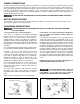
ADDITIONAL SPECIFIC SAFETY RULES FAILURE TO FOLLOW THESE RULES MAY RESULT IN SERIOUS PERSONAL INJURY. 1. 2. 3. 4. 5. 6. 7. 8. 9. DO NOT OPERATE THIS MACHINE until it is completely assembled and installed according to the instructions. A machine incorrectly assembled can cause serious injury. OBTAIN ADVICE from your supervisor, instructor, or another qualified person if you are not thoroughly familiar with the operation of this machine. Knowledge is safety.
POWER CONNECTIONS A separate electrical circuit should be used for your machines. This circuit should not be less than #12 wire and should be protected with a 20 Amp time lag fuse. If an extension cord is used, use only 3-wire extension cords which have 3prong grounding type plugs and matching receptacle which will accept the machine’s plug.
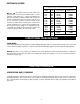
EXTENSION CORDS MINIMUM GAUGE EXTENSION CORD RECOMMENDED SIZES FOR USE WITH STATIONARY ELECTRIC MACHINES Ampere Rating Use proper extension cords. Make sure your extension cord is in good condition and is a 3-wire extension cord which has a 3-prong grounding type plug and matching receptacle which will accept the machine’s plug. When using an extension cord, be sure to use one heavy enough to carry the current of the machine.
2 3 1 4 5 6 7 8 15 20 22 21 9 16 17 18 10 19 13 12 11 14 1. Stock Feeder 13. 3/8 Lockwasher 2. Overarm 14. 3/8-16 x 1" Hex Socket Head Screw 3. Overarm Clamp Assembly 15. Housing 4. Swivel Joint 16. Pivot Ball Cover 5. Base 17. M10 x 50MM Hex Head Screws (3) 6. Pivot Ball 18. M10.2 Lockwasher (3) 7. Shaft 19. M10 Hex Nut (3) 8. 14MM and 17MM Open-end Wrench 20. M10 x 30MM Hex Head Screws (4) 9. T-Handle Screw 21. M10 Lockwasher (4) 10. Locking Lever 22.
ASSEMBLY ASSEMBLY TOOLS REQUIRED 7/16" Wrench 1/2" Wrench 3/8" Wrench 5/16" Wrench 4mm Hex Wrench Phillips Screwdriver ASSEMBLY TIME ESTIMATE Approximately 2-4 hours The Versa-FeederTM can be assembled as shown in Figs. 3 or Fig. 4, depending on the operation and type of woodworking machine on which the stock feeder will mount. The following instructions pertain to the assembly in Fig. 3. IMPORTANT: Familiarize yourself with the following assembly instructions and the components of the machine.
2. Place the pivot ball housing (F) Fig. 7 in the sleeve (G) of stock feeder. NOTE: Position the slot in the pivot ball housing (F) "up" (Fig. 8). 3. Insert the overarm (B) Fig. 9 with pivot ball (A) attached, through the housing (F) until the pivot ball (A) is inside the housing (F). Bring the overarm (B) Fig. 10 over and inside the slot in pivot ball housing (F). Push the pivot ball and the overarm (A) forward until the pivot ball is at the front of housing (F). 4.
5. Insert the metal shaft (J) Fig. 12 through the hole in the side of the sleeve (G) and into the wide slots of the pivot cover (H) Fig. 12. Thread the T-handle screw (K) Fig. 13 into the hole of the shaft (J), just enough to hold the pivot pin assembly in position. 6. Fig. 14 illustrates the pivot ball and overarm attached to the stock feeder. 7. Loosely thread three M10 x 50MM hex head screws (L) Fig. 15 into the holes in the overarm clamp assembly (M). 8. Insert an M8 hex nut (P) Fig.
9. Insert the end of the overarm assembly (B) Fig. 18 into the clamp assembly (M) until the gear inside the clamp assembly meshes with the rack on the overarm. Turn the T-handle screw (S) counter-rclockwise until the clamp assembly (M) is securely positioned on the overarm assembly (B). IMPORTANT: Depending on the application, the overarm assembly (B) can be inserted into either end of the clamp assembly (M). 10. Position three lockwashers and M10 hex nuts (T) Fig.
ALTERNATE ASSEMBLY ARRANGEMENT To assemble the Versa-FeederTM in the mounting arrangement shown in Fig. 4, attaching the pivot ball to the overarm clamp assembly differs slightly. To assemble: 1. 2. 3. 4. 5. Remove the overarm (A) Fig. 24 from the overarm clamp assembly (B). Remove the swivel joint (C) Fig. 24 and mounting bracket (D) from the clamp assembly (B). Remove the overarm (A) Fig. 25 from the housing (E). Remove the pivot ball (F) Fig. 26 from the angled end of the overarm (A).
6. Insert the straight end of the overarm (A) Fig. 29 through the housing (E). Attach the pivot ball (F) Fig. 29 to the overarm (A) with a 3/8-16 x 1" socket hex head screw and lock-washer (K) Fig. 30. NOTE: Make certain that the screw and lockwasher (K) are recessed inside pivot ball (F). 7. Push the pivot ball, attached to the overarm (A) Fig. 31, to the front of the housing (E). Place the cover (M) over the pivot ball (F) with the wider slots of the cover (M) positioned horizontally.
MOUNTING THE VERSA-FEEDERTM TO A MACHINE TABLE Decide on the location you wish to mount the Versa-FeederTM on your machine. Refer to Figs. 44, 45, and 46 for assistance when mounting the stock feeder assembly to a table saw, jointer, or shaper. To mount the stock feeder assembly to a machine table: 1. Position the mounting bracket (A) Fig. 35 at your desired location. 2. Mark the location where four mounting holes are to be drilled. 3.
MACHINE USE DISCONNECT MACHINE FROM THE POWER SOURCE. 1. You can rotate the entire feeder assembly (A) Fig. 38 360 degrees in the mounting bracket by loosening the locking lever (B). 2. To raise or lower the feeder assembly (A) Fig. 38 , loosen the lever (C) and move the overarm (D). 3. To move the feeder assembly (A) Fig. 38 in or out, loosen the locking lever (E) and rotate the T-handle screw (F). 4. To adjust the position of the stock feeder (A) Fig. 38, loosen the T-handle screw (G). 5.
REPLACING FEED ROLLERS Each feed roller is removable for repair or replacement. To remove the feed rollers: DISCONNECT MACHINE FROM THE POWER SOURCE. 1. 2. 3. 4. Loosen the three screws (A) Fig. 42 and remove the cover (B). Remove the retaining ring (C) Fig. 43, and lift off the feed roller (D). Replace the rollers. Replace the retaining rings, cover and screws. Fig. 43 Fig. 42 D A C B USING THE STOCK FEEDER ON A TABLE SAW A Position the feeder assembly (A) Fig.
USING THE STOCK FEEDER ON A SHAPER A Position the feeder assembly (A) Fig. 46 so that the shaper cutter is between the middle roller (B) and infeed roller (C). The outfeed roller (D) should be approximately 1/4" closer to the outfeed fence (E) than the infeed roller (C). E D B C Fig. 46 TROUBLESHOOTING For assistance with your machine, visit our website at www.deltamachinery.com for a list of service centers or call the DELTA Machinery help line at 1-800-223-7278 (In Canada call 1-800-463-3582).
KEEP MACHINE CLEAN LUBRICATION Periodically blow out all air passages with dry compressed air. All plastic parts should be cleaned with a soft damp cloth. NEVER use solvents to clean plastic parts. They could possibly dissolve or otherwise damage the material. Apply household floor paste wax to the machine table and extension table or other work surface weekly.
PORTER-CABLE • DELTA SERVICE CENTERS (CENTROS DE SERVICIO DE PORTER-CABLE • DELTA) Parts and Repair Service for Porter-Cable • Delta Machinery are Available at These Locations (Obtenga Refaccion de Partes o Servicio para su Herramienta en los Siguientes Centros de Porter-Cable • Delta) ARIZONA Phoenix 85013-2906 4501 N. 7th Ave.