(Model 36-902) PART NO. 422-27-655-0068 - 02-14-03 Copyright © 2003 Delta Machinery To learn more about DELTA MACHINERY visit our website at: www.deltamachinery.com. For Parts, Service, Warranty or other Assistance, please call 1-800-223-7278 (In Canada call 1-800-463-3582).
INTRODUCTION The model 36-902, 30" capacity Unifence™ Saw Guide can be assembled to the, Contractors Saw and Unisaw, in addition to other makes of table saws. The 36-902 Unifence Saw Guide includes the fence, carriage assembly, front guide rail, table frame and legs. The accessory 36-893 table for the 36-902 30" Unifence, is not included and must be ordered separately or a similar table must be constructed by following the instructions in this manual.
Fig. 2 Fig.
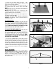
ASSEMBLING TABLE TO SAW 1. If your saw has a right extension wing, front and rear guide rails, they must be removed. 2. Lay the table upside down on the floor or bench, as shown in Fig. 4. Fig. 4 3. Assemble the two table legs (A) Fig. 5 to the bottom of the table using eight #8x7/8" self tapping screws supplied. NOTE: Refer to Fig. 2 for the hole location for the 36-902 30" Unifence. A Fig. 5 4. Insert foot adapter (T) Fig. 6, into the bottom of each leg (A).
. Fasten the front table support (F) Fig. 9, to the bottom of the table as shown using two #8x7/8" long wood screws (H) and (I) supplied. NOTE: The vertical flange, on the table board support (F), should be flush with the front edge of the table board. NOTE: The slots closer to the angles in the support (F) should be against the table. NOTE: Screws (H) and (I) Fig. 9 should not be completely tightened to the table board at this time. Screw (I) will have to be removed later.
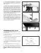
FOR DELTA TABLE SAWS ONLY 9. Fasten the table adapter plate (B) to the right side of the saw table. Place a 7/16" lockwasher onto a 7/1620x1" hex head screw (D), insert screw through the table adapter plate and thread screw into right side of saw table. Repeat this process for the two remaining holes. NOTE: Before tightening screws (D), use a straight edge to make sure top of the adapter plate (B) is level with or slightly below surface of the saw table.
12. Assemble the table (A) to the two brackets (J) on the rear table support (K) Fig. 16, using two #8x7/8" screws. J K A Fig. 16 13. Using a straight edge (S) Fig. 17, make certain the Unifence table surface is level with the saw table by adjusting two leveling screws located on the bottom of table legs and adjusting angle brackets (B) Fig. 13, use a level, side to side and front to back to make sure the table is level.
ASSEMBLING UNIFENCE GUIDE RAIL TO TABLE C 1. Locate the Guide Rail and mounting hardware from the packing material of the Unifence. 2. The guide rail has end caps inserted into each end of the rail. Remove the right end cap (B) Fig. 20, by inserting a flathead screwdriver (C) into the channel in front of the guide rail and press outward against the inside of the end cap (B) as shown. The end cap (B) will pop out.
6. Slide the guide rail along until the “0” on the Unifence scale is aligned with the right edge of the saw table. Snug the hex nuts on the saw and extension table but do not tighten at this time. H C 7. Adjust the guide rail (C) Fig. 25, parallel with the saw table surface. Place a square (H) on the saw table at both the left and right front ends of the table, with the rule of the square against the flat surface on top of the guide rail. The guide rail (C) Fig.
P R Fig. 29 ADJUSTING RAIL STOP 1. The Rail Stop Assembly Fig. 30, can be adjusted to any number of positions along the guide rail providing a quick stop setting for the Unifence body by loosening knob (G) and sliding the stop along the rail to the desired position and re- tighten. F 2. Any number of stops can be purchased and installed to provide time saving quick stop adjustment for the Unifence body. G Fig. 30 3. If flip stop does not retract fully the bolt (F) Fig.
ASSEMBLING UNIFENCE BODY TO GUIDE RAIL C E F B 1. Turn fence body (A) Fig. 34, upside down and lay it on a table or bench. Push handle (B) in against fence body. Make certain the surface (C) of clamp bracket is parallel to the face (D) of the fence body, and that the inside edge (E) of the clamp bracket is parallel to surface (F) of the fence body. Turn handle (B) Fig. 32, if necessary. D Fig. 34 2. Place fence body (A) Fig.
ASSEMBLING FENCE TO UNIFENCE BODY C 1. The fence (A) can be assembled to clamp plate (B) in either the horizontal position as shown in Fig. 38, or the vertical position as shown in Fig. 39. Make certain the two lock knobs (C), are loose and slide fence (A) onto clamp plate (B) as shown. Then tighten the two lock knobs (C). A B Fig. 38 C A B 2. For most normal ripping operations, the bottom of the fence should be positioned slightly above the table surface. Loosen two lock knobs (C) Fig.
3. When ripping thin stock, it is sometimes more convenient to use the fence in the horizontal position, as shown in Fig. 42. Fig. 42 4. To move the fence along the guide rail, lift up clamp lever (A), as shown in Fig. 43, slide fence to desired position on the rail, and push down on clamp lever (A) to lock fence in place. A Fig. 43 5. The distance the fence is positioned away from the blade is indicated by the two witness lines (B) and (C) Fig. 44, located on the cursor (D).
RIPPING WITH THE UNIFENCE A Ripping is the operation of making a lengthwise cut through a board, as shown in Fig. 46, and the rip fence (A) is used to position and guide the work. One edge of the work rides against the rip fence while the flat side of the board rests on the table. Since the work is pushed along the fence, it must have a straight edge and make solid contact with the table. The saw blade guard must be used.
ADJUSTING FENCE PARALLEL TO MITER GAGE SLOTS The fence (A) Fig. 50, should be adjusted so it is parallel to miter gage slots (B). To check and adjust, move the fence (A) until the bottom front edge of the fence is in line with the edge of the miter gage slot as shown, and push down on fence clamping lever (C). Check to see if the fence is parallel to the miter gage slot the entire length of the table.
RIPPING ON LEFT SIDE OF SAW BLADE C In some cases it may be desirable to use the fence on the left side of the saw blade. This is accomplished by repositioning the fence (A) Figures 54 and 55, fence clamp bar (B) and lock knobs (C) so that the fence (A) will be attached to the right side of the fence body, as shown in Fig. 55. The complete fence assembly (D) Fig. 55, can easily be moved to the left side of the saw table. A B Fig. 54 C A D Fig.
USING AUXILIARY WOOD FACING ON THE UNIFENCE It is necessary when performing special operations such as when using the moulding cutterhead to add wood facing (A) Fig. 59, to one side of the rip fence as shown. The wood facing is attached to the fence with wood screws through holes drilled in the fence. A suitable stock size for most work is 3/4", although an occasional job may require one inch facing. A Fig.
CONSTRUCTING A PUSH STICK 18 1/2" SQUARES CUT OFF HERE TO PUSH 1/2" WOOD CUT OFF HERE TO PUSH 1/4" WOOD NOTCH TO HELP PREVENT HAND FROM SLIPPING MAKE FROM 1/2" OR 3/4" WOOD OR THICKNESS LESS THAN WIDTH OF MAT’L. TO BE CUT PUSH STICK When ripping work less than 4 inches wide, a push stick should be used to complete the feed and could easily be made from scrap material by following the pattern shown.
ACCESSORIES A complete line of accessories is available from your Delta Supplier, Porter-Cable • Delta Factory Service Centers, and Delta Authorized Service Stations. Please visit our Web Site www.deltamachinery.com for a catalog or for the name of your nearest supplier. WARNING: Since accessories, other than those offered by Delta, have not been tested with this product, use of such accessories could be hazardous. For safest operation, only Delta recommended accessories should be used with this product.
PORTER-CABLE • DELTA SERVICE CENTERS (CENTROS DE SERVICIO DE PORTER-CABLE • DELTA) Parts and Repair Service for Porter-Cable • Delta Machinery are Available at These Locations (Obtenga Refaccion de Partes o Servicio para su Herramienta en los Siguientes Centros de Porter-Cable • Delta) ARIZONA Tempe 85282 (Phoenix) 2400 West Southern Avenue Suite 105 Phone: (602) 437-1200 Fax: (602) 437-2200 CALIFORNIA Ontario 91761 (Los Angeles) 3949A East Guasti Road Phone: (909) 390-5555 Fax: (909) 390-5554 San Leandro