
Instruction manual


10 - English
9. Attach the lower dust bag retaining clip (A) Fig. 13,
to the dust collector drum. Align the two holes (B) in
the retaining clip (A) Fig. 13, with the two holes in the
drum. Insert a 1/4-20 x 5/8" hex head screw through
the holes in the retaining clip and the holes in the
drum. Place a 1/4" flat washer onto the screws, and
thread 1/4-20 hex nuts on the screws and tighten
securely. Repeat this process for the three remaining
sides of the drum.
ASSEMBLING DUST INTAKE PORT AND
CAPS TO BLOWER AND MOTOR ASSEMBLY
Disconnect the machine from the
power source!
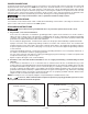
1. Align the four holes in dust intake port (A) Fig. 14,
with the mounting holes in flange (B) of blower and
motor assembly and fasten with four sheet metal
screws (C). Fig. 15 illustrates the dust intake port
assembled to the blower assembly.
2. NOTE: Two dust intake port caps (D) Fig. 16, are
supplied with the dust collector. The caps are to be
placed into the dust intake ports (E) when the intake
ports are not in use.
3. Place the collar of dust cap (D) Fig. 16, over the
opening on intake port. Press recessed side of
dust cap (D) into port opening. IMPORTANT: When
connecting an intake hose to one or both intake
ports, DO NOT REMOVE THE DUST CAP COLLARS
(F) FIG. 16 FROM THE INTAKE PORTS. Pull the dust
cap from the port opening and slide the collar and
cap farther onto the port housing.
A
B
C
Fig. 14
Fig. 15
E
D
E
D
F
Fig. 16
A
B
Fig. 13