½ H.P. Single-Stage Dust Collector (Model 50-850) PART NO. 902115 - 11-15-02 Copyright © 2002 Delta Machinery To learn more about DELTA MACHINERY visit our website at: www.deltamachinery.com. For Parts, Service, Warranty or other Assistance, please call ESPAÑOL: PÁGINA 15 RTD10000115AA 1-800-223-7278 (In Canada call 1-800-463-3582).
GENERAL SAFETY RULES Woodworking can be dangerous if safe and proper operating procedures are not followed. As with all machinery, there are certain hazards involved with the operation of the product. Using the machine with respect and caution will considerably lessen the possibility of personal injury. However, if normal safety precautions are overlooked or ignored, personal injury to the operator may result.
ADDITIONAL SAFETY RULES FOR DUST COLLECTORS WARNING: FAILURE TO FOLLOW THESE RULES MAY RESULT IN SERIOUS PERSONAL INJURY. 1. DO NOT OPERATE THIS MACHINE until it is assembled and installed according to the instructions. 14. DO NOT use the dust collector as a toy. DO NOT use near or around children. 2. OBTAIN ADVICE FROM YOUR SUPERVISOR, instructor, or another qualified person if you are not familiar with the operation of this machine. 15.
UNPACKING AND CLEANING Carefully unpack the tool and all loose items from the shipping container(s). Remove the protective coating from all unpainted surfaces. This coating may be removed with a soft cloth moistened with kerosene (do not use acetone, gasoline or lacquer thinner for this purpose). After cleaning, cover the unpainted surfaces with a good quality household floor paste wax.
ASSEMBLY WARNING: FOR YOUR OWN SAFETY, DO NOT CONNECT THE MACHINE TO THE POWER SOURCE UNTIL THE MACHINE IS COMPLETELY ASSEMBLED AND YOU READ AND UNDERSTAND THE ENTIRE INSTRUCTION MANUAL. ASSEMBLING CASTERS TO BASE B A 1. Insert threaded rod of caster (A) Fig. 4, into the hole located on the underside of base (B) and fasten with 3/8" lockwasher (C) and 3/8-16 hex nut (D). Fig. 5, illustrates the caster fastened to the base. C 2.
4. Assemble the remaining drum supports (F) Fig. 9, to base (A) as shown. F F 5. Assemble “U” bracket (H) Fig. 10, to drum (J). Place a 5/16" flat washer then a 5/16" lockwasher onto a 5/1618x5/8" hex head screw. Insert the hex head screw (K) thru the hole in the “U” bracket and the hole in the drum, thread a 5/16" hex nut onto the hex head screw and tighten securely. Repeat this process for the remaining hole. NOTE: “U” bracket should be mounted to the right side of opening (L) in drum as shown. A Fig.
9. Attach the lower dust bag retaining clip (A) Fig. 14A, to the dust collector drum. Align the two holes (B) in the retaining clip (A) Fig. 14A, with the two holes in the drum. Insert a 1/4-20x5/8" hex head screw through the holes in the retaining clip and the holes in the drum. Place a 1/4" flat washer onto the screws, and thread 1/4-20 hex nut s on the screws and tighten securely. Repeat this process for the three remaining sides of the drum. B A Fig.
ASSEMBLING FILTER AND DUST COLLECTION BAGS TO DRUM A B 1. Hook the loop on the top of filter bag (A) Fig. 18, onto filter bag support rod (B) as shown. 2. Assemble extension rod (C) Fig. 19, onto the end of filter bag support rod (B). Raise support rods (B) and (C), with filter bag (A) attached and place end of support rod (C) into holes of bracket (D). NOTE: Flared end of filter bag extension rod will prevent the rod from sliding through bracket. Fig. 18 B A D 3.
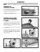
ASSEMBLING DUST INTAKE HOSES TO BLOWER AND MOTOR ASSEMBLY KEEP DUST CAPS INSTALLED AT ALL TIMES OVER INTAKE PORTS. REMOVE A DUST CAP ONLY WHEN A FLEXIBLE HOSE IS ATTACHED TO THE INTAKE PORT. The dust collector is supplied with a 4" dia. flexible dust intake hose. 1. To assemble the intake hose (A) Fig. 23, to the blower assembly, pull the dust cap (B) from the dust intake port (C) and slide the dust cap collar (D) farther onto the dust intake port (C) as shown.
240 VOLT, SINGLE PHASE OPERATION GROUNDED OUTLET BOX The motor supplied with your tool is a dual voltage 120/240 volt motor. If it is desired to operate your dust collector at 240 volts, single phase, contact your local Authorized Delta Service Center or qualified electrician for proper procedures to rewire your dust collector motor for 240 volt operation and wiring a 240 volt attachment plug to the power supply cord.
OPERATING CONTROLS WARNING: BEFORE OPERATING THE MACHINE, FOR OPERATOR SAFETY, ALWAYS MAKE CERTAIN THAT EACH DUST INTAKE PORT (WHICH IS NOT BEING USED OR PREVIOUSLY ASSEMBLED TO A DUST COLLECTION SYSTEM) BE COVERED WITH A DUST INTAKE PORT CAP. THE ROTATING FAN INSIDE THE BLOWER HOUSING IS ACCESSIBLE THROUGH THE DUST INTAKE PORTS AND IS HAZARDOUS. ALWAYS WEAR PROPER APPAREL, DO NOT WEAR JEWELRY, AND KEEP FINGERS AND ALL FOREIGN OBJECTS OUT OF THE DUST INTAKE PORTS.
ACCESSORIES A complete line of accessories is available from your Delta Supplier, Porter-Cable • Delta Factory Service Centers, and Delta Authorized Service Stations. Please visit our Web Site www.deltamachinery.com for a catalog or for the name of your nearest supplier. WARNING: Since accessories, other than those offered by Delta, have not been tested with this product, use of such accessories could be hazardous. For safest operation, only Delta recommended accessories should be used with this product.
PORTER-CABLE • DELTA SERVICE CENTERS (CENTROS DE SERVICIO DE PORTER-CABLE • DELTA) Parts and Repair Service for Porter-Cable • Delta Machinery are Available at These Locations (Obtenga Refaccion de Partes o Servicio para su Herramienta en los Siguientes Centros de Porter-Cable • Delta) ARIZONA Tempe 85282 (Phoenix) 2400 West Southern Avenue Suite 105 Phone: (602) 437-1200 Fax: (602) 437-2200 CALIFORNIA Ontario 91761 (Los Angeles) 3949A East Guasti Road Phone: (909) 390-5555 Fax: (909) 390-5554 San Leandro