Allen-Bradley Driver for DeltaV Programmable Serial Interface Card USER MANUAL May 2003 Rev. P1.7 Allen-Bradley and DeltaV are registered trademarks and DeltaV is a trademark of Emerson © Emerson 1998, 1999, 2000, 2001. All rights reserved. Printed in the U.S.A. While this information is presented in good faith and believed to be accurate, MYNAH Technologies does not guarantee satisfactory results from reliance upon such information.
Powerful Solutions for Digital Plants 1 INTRODUCTION 1.1 Scope This document is the User Manual for the Allen Bradley serial communication driver firmware for the Emerson DeltaV Control System; it provides information required to install, configure, and maintain the Allen-Bradley driver firmware on the DeltaV Programmable Serial Interface Card (PSIC).
Powerful Solutions for Digital Plants 1.2 Document Format This document is organized as follows: Introduction Describes the scope and purpose of this document Theory of Operation Provides a general functional overview of the Allen-Bradley Driver. Describes downloading procedures for the Allen-Bradley Driver firmware on to the DeltaV PSIC Downloading Firmware 1.
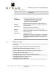
Powerful Solutions for Digital Plants Table 1: System Specifications Specifications Firmware Allen-Bradley Driver Firmware (P1.7) Protocol Allen-Bradley Protocol as defined in the documents: Data Highway/Data Highway PlusÔ/DH-485 Communication Protocol and Command Set Reference Manual by Allen-Bradley Compatibility Software Requirements DeltaV System Software (Release 3.
Powerful Solutions for Digital Plants 2 THEORY OF OPERATION As part of the serial interface port license, a standard Modbus protocol is installed on the DeltaV PSIC prior to customization. The PSIC needs to be flash upgraded from the Modbus protocol to the Allen-Bradley protocol before operation. The Allen-Bradley serial driver implements DF1 protocol. It communicates with PLC-3, PLC-5 or SLC5/XX devices on the DH+ network through either a 1785-KE or 1770-KF2 communication modules.
Powerful Solutions for Digital Plants With the Allen-Bradley driver installed, the “Advanced” tab under port properties will allow selection of the configuration option for the port to act as a slave. This Allen-Bradley driver does not support slave functionality, so this configuration option is not valid. The Allen-Bradley driver supports PLC-5 Logical ASCII and binary addressing, and SLC5/XX Protected Typed Logical addressing.
Powerful Solutions for Digital Plants 3 Downloading the firmware To begin installation of the Allen-Bradley driver, create a folder on the hard drive. The preferred location for the folder is at C:\DeltaV\Ctl\ProgSerial\AllenBradley, although any location will work. Next, copy the eight files from the diskette provided. Those files are: 1200.idf IO_Compatibility.csv AllenBradleyApp.sdf AllenBradleyApp.hex SerBoot.hex SerReleaseApp.hex StandardModbusApp.sdf Ab-manual.
Powerful Solutions for Digital Plants 4 CONFIGURATION INFORMATION This section describes the steps necessary to configure the DeltaV PSIC and the AllenBradley PLC such that communications may be invoked 4.1 Channel Attributes Block of PSIC Channel Attributes Block For the PSIC configuration, there is one channel attributes block per Dataset. There can be up to 16 Datasets configured per port for a total of 32 Channel Attribute Blocks per Serial Card.
Powerful Solutions for Digital Plants Attribute Defined Values 0 = Basic Protected DeviceDataType 1 = Basic Protected Bit 2 = Basic Unprotected 3 = Basic Unprotected Bit 4 = PLC-5 Typed (Logical ASCII Addressing) 5 = PLC-5 Ranged (Logical ASCII Addressing) 6 = Diagnostic 7 = PLC-5 Read-Mod-Write (Logical ASCII Addressing) 8 = PLC-5 Typed (Logical Binary Addressing) 9 = PLC-5 Ranged (Logical Binary Addressing) 10 = PLC-5 Read-Mod-Write (Logical Binary Addressing) 11= SLC 500, SLC 5/03 and SLC 5/04 Protec
Powerful Solutions for Digital Plants Specify 0 for DF1 with Full Duplex and BCC SpecialData3 Specify 1 for DF1 with Half Duplex and CRC When using a 1770-KFC15 gateway device, use this Extra Hop parameter to access the ControlNet address of the CNB module. The DeltaV PSIC device address must be between 1-50. This parameter has only the following values: SpecialData4 1. 100 for ControlNet node in slot 0. 2. 150 for ControlNet node in slot 1. 3. 200 for ControlNet node in slot 2.
Powerful Solutions for Digital Plants affecting other bits in the same word. This command is not available under the SLC5/XX architecture. 4.2.3 DeviceDataType This attribute defines what type of transaction will be performed for the Dataset between the PSIC and the Allen-Bradley device Values from 0 to 11 are listed in the above table. They are briefly described below: MYNAH Technologies 504 Trade Center Blvd. Chesterfield, MO 63005 www.mynah.
Powerful Solutions for Digital Plants Types 0 – 3 (Basic Commands): These are mainly for PLC-5 backward compatibility to older types of PLC with non-paged memory like PLC-2. The special data fields are not used during configuration. All data (16-bit integer or discrete) are written/read through the PLC-2 compatibility file. The memory address in PLC-5 is assigned with the communication module address. This address is an octal based number which can be set with dip switches on the module.
Powerful Solutions for Digital Plants Types 5 (Ranged Transaction with ASCII addressing) and 9 (Ranged Transaction with binary addressing): Unlike Typed operations that automatically adjust the memory address to accommodate the defined element type, the Ranged operations use word address exclusively. It performs consecutive memory word read and write. The driver takes care of address adjustment for floating point file type, making it transparent to the user and DeltaV.
Powerful Solutions for Digital Plants For floating point values, the starting address refers to the register number and a 4 byte value is read/written. For all other tables, the starting address refers to the register number and a 2 byte value is read/written. Notes: 1. DeviceDataTypes 7 and 10 are only valid with file type 3 and output mode 1. 2. Output Modes : 0- block output; 1- single data output 3. PLC 5/XX Binary File Types only work in output mode 0, block outputs.
Powerful Solutions for Digital Plants 4.3 Dataset Configuration Display The following DeltaV screens are displayed during a typical PSIC configuration utilizing the above parameters: MYNAH Technologies 504 Trade Center Blvd. Chesterfield, MO 63005 www.mynah.
Powerful Solutions for Digital Plants MYNAH Technologies 504 Trade Center Blvd. Chesterfield, MO 63005 www.mynah.
Powerful Solutions for Digital Plants MYNAH Technologies 504 Trade Center Blvd. Chesterfield, MO 63005 www.mynah.
Powerful Solutions for Digital Plants 4.4 Serial Port Configuration for DeltaV PSIC In order for proper communication between the Programmable Serial Interface Card and the Allen-Bradley PLC, the serial port settings on both devices must be configured properly. The PSIC serial port can be configured via a combination of the following settings through the DeltaV Explorer Menu using the Properties box.
Powerful Solutions for Digital Plants · Stop Bits 1 or 2 5 Operational Check 5.1 Scope The following sections provide some assistance to ensure the interface is working properly. 5.2 Verify Hardware and Software Version Number The user can verify that the AB driver has been installed using the DeltaV Diagnostics tool. The Diagnostics tool will show the Hardware Revision No. (HwRev) and the Software Revision No. (SwRev).
Powerful Solutions for Digital Plants · To assign a Dataset and a register in the Dataset to an I/O module, follow these steps: 1. Double click the IO_IN/IO_OUT parameter for the module. This brings up the IO_IN/IO_OUT Property window. 2. Click on the Browse button. This brings up the Browse window. 3. Click on the Object_Type drop down list, select All. This displays all the Dataset tags. 4. Double click on the desired Dataset tag. This assigns the tag to the module and closes the Browse window. 5.
Powerful Solutions for Digital Plants 6 DeltaV – PLC/SLC Electrical Interface The electrical interface between DeltaV and the PLC-3, PLC-5 and SLC 5/XX conforms to the RS-232 protocol and RS-422/485 protocol. The cabling should not exceed 50 feet for the RS-232 protocol or 4000 feet for the RS-422/485 protocol. In 6.1 and 6.2 the pin assignments for the PSIC Serial Terminal Block are listed for the RS-232 protocol and the RS-422/485 protocol.
Powerful Solutions for Digital Plants 6.
Powerful Solutions for Digital Plants 6.3 Wiring Connections for RS-232 Communications The figure below shows the connections between the 1785-KE module RS-232 port and the serial card I/O termination block. Serial Card Term.
Powerful Solutions for Digital Plants The figure below shows the connections between the Channel 0 Port of a PLC-5/PLC-3 and the serial card I/O termination block. Serial Card Term. Block P1 P2 PLC-5 Channel 0 25-pin RS-232 Port Shield 1 (GND) 1 9 7 (GND) (TXD) 3 11 (RXD) 5 13 (DTR) 7 15 3 (RXD) 2 (TXD) 6 (DSR) 8 (DCD) 20 (DTR) 4 5 (RTS) (CTS) (DSR) 8 16 The figure below shows the connections between the Channel 0 Port of a SLC5/XX and the serial card I/O termination block.
Powerful Solutions for Digital Plants Appendix A Module Settings Appendix A discusses the necessary settings for 2 gateway modules. The 1785-KE module, Series A and B, and the 1771-KE and 1771-KF modules. A.1 1785-KE Module (Series A) Switch Settings The 1785-KE module (Series A) has 6 switch assemblies which allow the selection of various communications options.
Powerful Solutions for Digital Plants There are additional switches on the 1785-KE Module (Series B) which may require adjustment. Refer to the Allen-Bradley User Manual for further information. A.3 · SW1 - RS232C link features · SW2 - Node number · SW3 - Data highway Plus and RS-232C communication baud rates, and Local/Remote option · SW4 - Reserved for future use.