
User guide

RMC100 and RMCWin User Manual
5-22
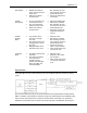
0 1 1 3 3
1 0 0 4 4
1 0 1 5 5
1 1 0 6 6
1 1 1 7 7
5.1.6.6 Using Parallel Event Mode
Note: This mode is available only in firmware version 19980706 and later.
This mode is intended for use with devices that can provide parallel outputs, such as PLCs and
thumb-wheel switches. Commands may be given to up to four axes at a time, which is useful for
PLCs whose scan times are too long to use Parallel Position mode—which can issue only one
command per scan—and Command mode—which can issue a command every two scans.
This mode utilizes the RMC’s Event Control feature; you should be familiar with this feature
before using this mode. Each command consists of an 8-bit Event Control step number for the
receiving axis to begin executing and a Trigger input.
When used with thumb-wheels, some or all step-number inputs should be tied to the thumb-
wheel, and a push-on/push-off button should be tied to the Trigger input.
Refer to Features Shared by All Modes for details on input and output assignments that are
common to all modes.
Basic Operation
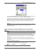
This mode is unique in that it can utilize both the Communication DI/O and Sensor DI/O. Each of
the DI/O modules can command two axes. When a command is given in Parallel Event mode, an
event sequence begins on the commanded axis at the Event Step number given on the inputs.
The following input/output assignments are used:
CPU DI/O:
Input 0
Run/Stop. Described in Features Shared by All Modes.
Input 1
Unused.
Output 0
Ready. Described in Features Shared by All Modes.
Output 1
Acknowledge. Described in Features Shared by All Modes.
Communication DI/O:
Inputs 0-7
Axis 0 Command Event Step (in binary)
Inputs 8-15
Axis 1 Command Event Step (in binary)