DeltaNode Solutions Fiber-DAS MANUAL Release 12-03 Copyright © 2012 DeltaNode® Solutions Ltd.
DELTANODE FIBER DAS MANUAL System Part Number Explanation Examples: DDR4-GC0-PA1-AD 4 band, 33dBm power output per band, Full band 700 combined with Cell 850 non duplexed, PCS combined with AWS duplexed, AC powered, 7/16 DIN, 1310nm uplink DDR4-GC0-PA1-AD-B12-C34-WUBCS 4 band, 33dBm power output per band, Full band 700 combined with Cell 850 non duplexed, PCS combined with AWS duplexed, AC powered, 7/16 DIN, Bands 1 and 2 (700 and 850) 1290nm uplink, Bands 2 and 3 (PCS & AWS) 1310nm uplink, CWDM, fiber sp
DELTANODE FIBER DAS MANUAL Contents System Part Number Explanation ............................................................................................................ 1 1 2 Introduction..................................................................................................................................... 4 1.1 Definitions ............................................................................................................................... 5 1.2 RF on fiber ..............
DELTANODE FIBER DAS MANUAL 5 4.1 Health and Safety .................................................................................................................. 38 4.2 Installing the Master Unit and Remotes ............................................................................... 39 Commissioning .............................................................................................................................. 39 5.1 6 Preparations ..............................................
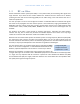
DELTANODE FIBER DAS MANUAL 1 Introduction This manual contains both guidelines on how to design a system using the DeltaNode Fiber-DAS concept and how to install, commission and maintain such a system for the life span of the entire installation. It will also contain many bits of information regarding general practices in the industry as well as other information.
DELTANODE FIBER DAS MANUAL 1.1 Definitions Here is a list of the abbreviations, industry standard lingo and acronyms used in this document. It is supposed to be a help for the reader and a reference section. BGW BIU BTS DAS DL Downlink Fiber Fiber-DAS FOI FOR GSM iDEN LTE MU POI QMA RBS RGW RU SC-APC Base station Gateway Base station interface. Also known as the DIU.
DELTANODE FIBER DAS MANUAL Single mode fiber SMA Switch TETRA UL UMTS Uplink SC-PC SC-UPC RF WCDMA W-CDMA A fiber where the light at a specified range of wavelengths only have a single path through. This is required for analogue modulated systems such as the DeltaNode FiberDAS system SubMiniature version A. A Type of RF Connector. A network switch is a computer networking device that connects devices together on a computer network. Terrestrial Trunked Radio.
DELTANODE FIBER DAS MANUAL 1.2 RF on fiber A fiber distributed antenna system (Fiber-DAS) is a very efficient way of transmitting radio signals over large distances. Up to about 25 km of fiber between the head-end and the remote unit is allowed, providing that the radio access technology (RAN) do not suffer timing issues and that the fiber loss is within the specification.
DELTANODE FIBER DAS MANUAL 2 System Description The Fiber-DAS system consists of two major parts. This is the Master Unit (MU) and one or more Remote Units (RU) connected to the Master Unit via optical fibers. Each Remot Unit needs to be connected to a fiber, but up to four RU:s can share a single fiber link using optical splitters. 2.1 Master Unit The Master Unit consists of a 19 inch frame rack with modules that are selected depending on the system design.
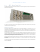
DELTANODE FIBER DAS MANUAL 2.1.1 MFU – Master Frame Unit The Master Frame Unit houses the other modules such as power supplies, fiber-optic interface cards and base station interface units. Figure 1: Master Unit The frame in the picture shows a frame equipped with 3 base station interface units, 6 fiber-optic interface cards and one power supply.
DELTANODE FIBER DAS MANUAL Specifications Parameter Input voltage Power connector Ethernet connector Weight (without modules) Temperature range Width Height Depth Molex Operational 16U PSU BIU FOI Maximum number of modules supported Temperature range 2.1.2 28 10 RJ45 2,5 0-45 19 3 300 4 8 16 0-45 VDC Pin kg °C Inch U Mm Pcs Pcs Pcs °C BIU – The Base Station Interface The BIU is the interface between the operator’s base station and the Fiber-DAS system.
DELTANODE FIBER DAS MANUAL The BIU is technology neutral and in the downlink path contains only settable attenuators that can be used to adjust the signal strength to proper levels before feeding them into the POI. In the uplink there is an amplifier followed by a settable attenuator used to adjust the signal and the noise level into the base station uplink. All connections necessary are made from the front of the BIU itself.
DELTANODE FIBER DAS MANUAL Standard variants of the BIU ArtNo Configuration DBI303 DBI307 DBI308S DBI308 DBI309 DBI318 DBI319 DBI320 DBI321 2 x TETRA 390 MHz* 2 x 700 MHZ ABC-band 2 x SMR 800 2 x 850 MHz 2 x 900 MHz 2 x 1800 MHz 2 x 1900 MHz 2 x UMTS 2100 MHz 2 x AWS 2100 MHz UL MHz 380-385 698-716 806-825 824-849 880-915 1710-1785 1850-1910 1920-1980 1710-1755 DL MHz 390-395 728-746 851-870 869-894 925-960 1805-1880 1930-1990 2110-2170 2110-2155 BTS I/F Duplex Duplex Duplex Duplex Duplex Duplex Duple
DELTANODE FIBER DAS MANUAL LED behavior The unit has two LEDs located on the front panel. One is the power on LED (green) and the other is the alarm LED (red). Both LEDs can indicate a number of states by different flashing behaviors. In an error state the web interface should be used to check the actual condition of the BIU but the LEDs on the front can give you a quick indication on the state of the unit. It is also useful for locating the physical unit if you have several BIUs installed in the same rack.
DELTANODE FIBER DAS MANUAL 2.1.3 POI – The Point of Interconnect Basically this is a 1U high unit that contains 4 1:8 splitters and some attenuators. This is a coupling field used to tie together the signals between the BIUs and the FOIs in a multiple band or multiple operator system. A COMMON C 1 2 3 4 5 6 7 8 POI DIU-304 B COMMON COMMON 1 2 3 4 5 6 7 8 1 2 3 4 5 6 7 8 D 1 2 3 4 5 6 7 COMMON 8 Each of the 4 fields has a COMMON port and ports 1-8.
DELTANODE FIBER DAS MANUAL Safety and Care for fibers The laser is a Class 3b laser that produces invisible infra-red coherent light. Avoid looking into connected fibers and receptacles. Not safe to view with optical instruments. Always put the protection caps on not used fibers and receptacles. Every time a fiber is disconnected and re-connected care should be taken to avoid dust to settle on the connector or in the receptacle.
DELTANODE FIBER DAS MANUAL Below is a block schematic that shows the downlink path in the FOI and how the test port is connected. As you can see there are two attenuators that can be set in the DL path, this allows for balancing the input signals from two different signal sources so that they can share the dynamics of the laser properly. The RF drive levels are measured and accessible in the web interface so that they can be checked. In the future alarm levels may be added to these test points.
DELTANODE FIBER DAS MANUAL Interfaces of the FOI Opto In/Out OPTO IN/OUT This is the receptacle for the optical fiber. The illustration shows the module with built in WDM (combined Rx/Tx). The version without WDM has a second connector where one is the Tx and the other is the Rx. UL OUT1 TP UL UL OUT2 DL IN1 TP DL DL IN 2 ON ALM UL OUT 1/2 These are the RF ports that normally are patched to the POI for interconnecting and then on to the BIU.
DELTANODE FIBER DAS MANUAL Parameter DOI 301 DOI 302 (WDM) DOI 308x Wavelength 1310 nm Rx and Tx separate 1310 nm Rx and Tx on sam fiber Separate Rx and Tx various wavelengths available Table 8: FOI variants The DOI 308 version can be ordered with various wavelengths. The actual wavelengths that are possible to are available upon request to info@deltanode.com. 2.1.5 PSU – the rack power supply The power supply unit can handle up to one full shelf of other active units, such as BIU or FOI.
DELTANODE FIBER DAS MANUAL If the BGW is replaced the Remote Units may not show up immediately. This is due to the lease time on the address they have. Eventually they will request a new address and when this is done they will show up. The BGW is the unit responsible for alarm handling and remote forward of alarms either by SMTP mail forwarding or by SNMP traps. A MIB file for your SNMP system is available from DeltaNode upon request as well as documentation regarding SNMP.
DELTANODE FIBER DAS MANUAL 2.1.7 RGW – the compact remote gateway The RGW is a small unit similar to the BGW but intended for small systems where there is a low number of remotes or where there is no head-end and therefore the RGW has a form factor that allows it to be mounted inside a repeater casing. This can be used to run up to 4 Remote Units from a single Repeater on a single Fiber.
DELTANODE FIBER DAS MANUAL Below is a list of the most common remote units that are used with the DeltaNode Fiber-DAS system. Variants are available upon request. Commonly for all Remote Units is their excellent noise figure, contributing to an overall noise figure for the whole system from remote to head-end into the base station of < 3 dB for the RF link. Both chassis comply with IP65 protection for use in any environment. The coating is a durable coating which aids the convection cooling.
DELTANODE FIBER DAS MANUAL SPECIFICATIONS DDR300(Triple Band) & DDR400(Quad Band) Power Consumption, max DDR 300 (400) 270 (360) W Dimensions WxDxH 300 x 220 x 700 mm < 24 Kg Weight AVAILABLE PRODUCTS, EUROPEAN CELLULAR System TETRA, Public Safety TETRA, Commercial TETRA, Commercial CDMA450 GSM-R EGSM900 GSM1800 UMTS UL Frequency MHz 380 - 385 410 - 415 415 - 420 453 - 457,5 876 - 880 880 - 915 1710 - 1785 1920 - 1980 DL Frequency MHz 390 - 395 420 - 425 425 - 430 463 - 467,5 921 - 925 925 - 9
DELTANODE FIBER DAS MANUAL SPECIFICATIONS DDR300 (Triple Band) & DDR400 (Quad Band) Power Consumption, max Dimensions Weight DDR 300 (400) WxDxH 270 (360) 300 x 220 x 700 < 24 AVAILABLE PRODUCTS, AMERICAN CELLULAR UL Frequency MHz 698 - 716 746 -776* 806 - 824 824 - 849 1850 - 1915 1710 - 1755 System LTE LB LTE UB iDEN Cellular PCS1900 AWS DL Frequency MHz 728 - 746 776 – 806* 851 - 869 869 - 894 1930 - 1995 2110 - 2155 W mm Kg Pout, DL, dBm (Composite) 33 33 33 33 33 33 Standard FCC FCC FCC FCC F
DELTANODE FIBER DAS MANUAL 2.2.2 DDS Deltanode’s DDS series distributed high power radio head is a high performing wideband radio head equipped with a Pre Distortion power amplifier that supports all modulations. The light weight, convection cooled IP65 chassis secures the performance in almost any environment.
DELTANODE FIBER DAS MANUAL 2.2.3 DDH Deltanode’s Distributed High power radio head is a high performing wideband radio head equipped with a feed forward multi carrier power amplifier that supports all modulations. The light weight, convection cooled IP65 chassis secures the performance in almost any environment.
DELTANODE FIBER DAS MANUAL FCC standards GENERAL SPECIFICATIONS Noise Figure Delay excluding optical fiber Power Supply Operating Temperature Casing OPTICAL SPECIFICATIONS RF Frequency range Flatness Optical output power DFB Laser output Wavelength Optical return loss Optical isolator Side-mode suppression ratio Maximum optical input power Typical 3 < 0,5 85 – 264 -25 - +55 IP65 Mains 88 – 2200 +- 3 Nominal 3 1270 - 1610 < -40 Min 30 Min 30 non destructive 10 SPECIFICATIONS DDH100(Single Band) Power
DELTANODE FIBER DAS MANUAL 2.2.4 DMU – Remote head end Deltanode’s DMU100 series is pickup repeater that can provide the signals over fiber to a Master Unit or directly to up to 4 Remote Units.
DELTANODE FIBER DAS MANUAL 3 System design Fiber-DAS is a way of distributing radio signals from a base station to a remotely located antenna where the coaxial cable losses would be too high or there is impractical to install coaxial cables. Fiber-DAS can be used indoor to cover large building where outside penetration of radio signals is not enough, it can be used to cover structures such as tunnels for rail and road, airports, metro lines and many other places.
DELTANODE FIBER DAS MANUAL If you are using radiating cables, then calculate with the loss over the maximum length of radiating cable you need to support and find the Remote Unit that has the highest total loss from the User Equipment (mobile station) to the Base Station end. 3.2.1 Downlink For the downlink you can usually just use the output power of the remote unit and then calculate your link budget.
DELTANODE FIBER DAS MANUAL Antenna Remote Unit Fiber RU -80 dBm FOI Card POI unit BIU Base Station FOI POI BIU BTS 50 dB -40 dB 20 dB -35 dB 7 dB -2 dB -30 dBm -70 dBm -50 dBm -85 dBm -78 dBm -80 dBm In the illustration above there is an input signal to the remote of -80 dBm.
DELTANODE FIBER DAS MANUAL 3 4,0 -5 -1 Total 4,1 Similar to a BTS own NF This is similar to the BTS own noise figure which generally is 2-4 dB depending on the system. This kind of desensitization then becomes a tradeoff between coverage area in the uplink and the noise load on the base station.
DELTANODE FIBER DAS MANUAL Fiber DAS thermal noise floor Noise figure DAS link Number of equal links System net gain DAS Noise result Noise load on BTS with DAS Desensitization on BTS New BTS Sensitivity Loss from BTS to remote antenna Sensitivity at remote antenna Fading margin Penetration loss Antenna gain MS Body loss MS Required signal level MS Output power Allowed path loss from MS to antenna -121,0 3,0 3,0 0,0 -118,0 -115,0 3,0 -106,0 7,0 -99,0 6,0 0,0 1,0 5,0 -89,0 30,0 119,0 dBm dB pcs dB dBm dBm
DELTANODE FIBER DAS MANUAL EIRP MS Uplink net gain Sensitivity at RU port Splitloss from antenna to RU Cable losses from antenna to RU DAS antenna gain Antenna sensitivity Allowed pathloss uplink Balance downlink-uplink 3.3 23,0 -10 -117,9 6,0 4,0 3,0 -110,9 133,9 4,0 dBm dB dBm dB dB dB dBm dB Multiple bands The flexibility of the system allows for up to 4 bands in one remote for the low and medium power remote units.
DELTANODE FIBER DAS MANUAL The above illustration shows two BIU cards interfacing with two Radio Base Stations. In this case they could be a 900 GSM station and one 1800 GSM station as an example. It could in fact be any combination of service and frequency band such as LTE-900 or WCDMA 850. Each BIU has a combined UL/DL port towards the base station and on the other side there are separate UL/DL ports. The BIU has an uplink amplifier and a downlink attenuator that can be set.
DELTANODE FIBER DAS MANUAL Here is a schematic on how this can be achieved: 3.5 Full system example Here is an example of a full system showing the Master Unit and the fibers that goes off to the Remote Units (not shown in this example) with multiple operators and a large number of frequency bands.
DELTANODE FIBER DAS MANUAL Block 3: These are the fiber-optic interfaces (FOI) and in this example up to 16 FOI cards may be connected for a total of 16 Remote Units if there are one Remote Unit per fiber. It is possible to use up to four Remote Units on a single fiber.
DELTANODE FIBER DAS MANUAL The third shelf is the FOI cards, up to 16 cards can be held in one such frame. Then there is the BGW computer tying all the communication together and providing the web interface for setting up and controlling the system. The BGW also has an optional “northbound” firewalled connection that can be connected to your own network for remote supervision, alarm and control. It can even be tunneled over the Internet providing there is a CGW unit where the tunnel terminates.
DELTANODE FIBER DAS MANUAL 4 Installation guidelines WARNING This is NOT a consumer device. It is design for installation by FCC LICENSEES and QUALIFIED INSTALLERS. You MUST have an FCC LICENSE or express consent of an FCC licensee to operate this device. You MUST register Class B signal boosters (as defined in 47 CFR 90.219) online at www.fcc.gov/signal-boosters/registration.
DELTANODE FIBER DAS MANUAL 4.2 Installing the Master Unit and Remotes All equipment must be properly grounded. This means that the ground peg in the mains connector for both head-end gear (Master Unit) and remote gear (Remote Units) must be connected to Phase, Neutral and Ground in a proper way before the plug is inserted in the unit. The chassis of the remote and the rack of the master unit should be grounded to a potential bar or safety grounding bar when operated.
DELTANODE FIBER DAS MANUAL 6 RF Commissioning In order to make the process more clear for this part of the manual we will consider setting up a fictitious system, but based on a standard approach at doing Fiber-DAS. The system that we are considering will have two frequency bands, let’s assume GSM 900 MHz and UMTS 2100 MHz. The example will have 2 sectors with two remotes in each sector.
DELTANODE FIBER DAS MANUAL 6.1.1 Noise load on Radio Base Station The system will inevitable add some noise to the receiver. Properly set up the noise figure in a system like this will be better than 3 dB. However, if the gain is set up poorly (not enough gain in the remote, too much gain in the head-end) it is possible to create a very bad noise figure. In order to avoid this the Fiber-DAS Calculator should be used to calculate the noise figure of the system in the uplink.
DELTANODE FIBER DAS MANUAL to reflect this. In general we should lower our so that we desensitize the BTS only about 3 dB. This value is a good compromise and similar to adding a second antenna to the same receiver port (which is kind of what we are doing with the Fiber-DAS).
DELTANODE FIBER DAS MANUAL Master Unit Fiberoptic Interface Remote Unit Antenna RU Fiber Point of interconnect FOI RU FOI RU FOI RU FOI POI Base station interface BIU Base Station C RBS Base station Coupler Spec. Turn on the RF Connect to the BIU and turn on the RF. Set the attenuator in the medium range for the uplink that you are measuring. This allows you later to adjust it up and down as necessary to get the correct gain for the uplink chain. Setting them to 10 dB is a good idea.
DELTANODE FIBER DAS MANUAL In this screen you should also turn RF on, set the gain to about 35 dB as a starting point and then turn on the uplink test tone. Note the frequency of the test tone, this is the frequency you should be measuring on your spectrum analyzer. Turn on the spectrum analyzer, make sure it is connected to the right port on the right BIU and then find the frequency. A reasonable span is 1 MHz and the receiver band width can be set to 30 kHz or similar.
DELTANODE FIBER DAS MANUAL We wanted -10 dB so we have 9,3 dB too low gain. We should then increase the gain and the best place to do this would be in the remote unit by setting the gain at 35 + 9,3 = 44,3 which we will round to 44 dB. That uplink is now finished and we will repeat the settings for all of our uplinks, one at a time.