2-04 AS20008, Rev 3 DOING OUR BEST TO PROVIDE YOU THE BEST 55 GALLON SKID MOUNT LAWN AND GARDEN SPRAYER OPERATORS MANUAL ASSEMBLY CALIBRATION OPERATION REPLACEMENT PARTS READ complete manual CAREFULLY BEFORE attempting operation. DEMCO Dethmers Mfg. Co. 4010 320th St. P.O. Box 189 Boyden, IA 51234 PH: (712) 725-2311 Toll Free: 1-800-543-3626 FAX: 1-800-845-6420 www.demco-products.
Thank you for purchasing a Demco sprayer. We feel you have made a wise choice and hope you are completely satisfied with your new piece of equipment. If you have any questions regarding applications of certain solutions or chemicals, contact your chemical supplier and follow chemical manufacturer recommendations as well as all licensing and use restrictions or regulations. WARNING: TO AVOID PERSONAL INJURY OR PROPERTY DAMAGE, OBSERVE FOLLOWING INSTRUCTIONS: Chemicals are dangerous.
Warranty Registration Dethmers Manufacturing Company 4010 320th Street • Box 189 • Boyden, Iowa 51234 Toll Free 800-54DEMCO (800-543-3626) • FAX 800-845-6420 www.demco-products.
Postage Dethmers Manufacturing Company 4010 320th Street, Box 189 Boyden, Iowa 51234 Page 4
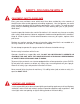
SAFETY TAKE NOTE! THIS SAFETY ALERT SYMBOL FOUND THROUGHOUT THIS MANUAL IS USED TO CALL YOUR ATTENTION TO INSTRUCTIONS INVOLVING YOUR PERSONAL SAFETY AND SAFETY OF OTHERS. FAILURE TO FOLLOW THESE INSTRUCTIONS CAN RESULT IN INJURY OR DEATH. THIS SYMBOL MEANS ATTENTION BECOME ALERT YOUR SAFETY IS INVOLVED! SIGNAL WORDS Note use of the following signal words DANGER, WARNING, and CAUTION with safety messages.
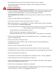
SAFETY...YOU CAN LIVE WITH IT EQUIPMENT SAFETY GUIDELINES Every year many accidents occur which could have been avoided by a few seconds of thought and a more careful approach to handling equipment. You, the operator, can avoid many accidents by observing the following precautions in this section. To avoid personal injury, study the following precautions and insist those working with you, or you yourself, follow them.
SAFETY SIGN LOCATIONS Types of safety sign and locations on equipment are shown in the illustration below. Good safety requires that you familiarize yourself with various safety signs, type of warning, and area or particular function related to that area, that requires your SAFETY AWARENESS. WARNING To prevent serious injury or death This decal is located near the sprayer lid. Replacement part # is AB21014.
SAFETY SIGN CARE Keep safety signs clean and legible at all times. Replace safety signs that are missing or have become illegible. Replacement parts that displayed a safety sign should also display current sign. Safety signs are available from your distributor, dealer parts department, or factory. How to install safety signs: Be sure that installation area is clean and dry. Decide on exact position before you remove backing paper. Remove smallest portion of split backing paper.
Move tractor wheels to widest recommended settings to increase stability. Do not allow anyone to stand between tongue or hitch and towing vehicle when backing up to sprayer. DURING OPERATION Beware of bystanders, PARTICULARLY CHILDREN! Always look around to make sure that it is safe to start engine of towing vehicle or move sprayer. This is particularly important with higher noise levels and quiet cabs, as you may not hear people shouting.
FOLLOWING OPERATION Following operation, or when unhitching, stop tractor or towing vehicle, set brakes, disengage PTO and all power drives, shut off engine and remove ignition key. Store unit in an area away from human activity. Do not park equipment where it will be exposed to livestock for long periods of time. Damage and livestock injury could result. Do not permit children to play on or around stored unit.
REMEMBER Your best assurance against accidents is a careful and responsible operator. If there is any portion of this manual or function you do not understand, contact your local authorized dealer or manufacturer. PERFORMING MAINTENANCE Good Maintenance is your responsibility. Poor maintenance is an invitation to trouble. Make sure there is plenty of ventilation. Never operate engine of towing vehicle in a closed building. Exhaust fumes may cause asphyxiation.
BOLT TORQUE TORQUE DATA FOR STANDARD NUTS, BOLTS, AND CAPSCREWS. Tighten all bolts to torques specified in chart unless otherwise noted. Check tightness of bolts periodically, using bolt chart as guide. Replace hardware with same grade bolt. NOTE: Unless otherwise specified, high-strength Grade 5 hex bolts are used throughout assembly of equipment. Bolt Torque for Standard bolts * Torque Specifications A 1/4 5/16 3/8 7/16 1/2 9/16 5/8 3/4 7/8 1 GRADE 2 lb-ft (N.m) GRADE 5 lb-ft (N.
FRAME ASSEMBLY PARTS BREAKDOWN AND PARTS LIST 3 17 16 5 19 3 14 15 5 12 5 19 4 10 13 3 9 18 3 3 9 18 5 5 18 6 11 3 FRAME ASSEMBLY PARTS LIST REF. NO. 1. 2. 3. 4. 5. 6. 7. 8. 9. 10. 11. 12. 13. 14. 15. 16. 17. 18. 19. - PART NO. 04340 04341 00907 00004 02592 04339 04346 04348 04347 02645 00095 04352 02802 04342 04344 04345 05034 00059 5316 04353 05785 QTY.
55 GALLON SPRAYER with GAS ENGINE DRIVEN ROLLER PUMP PLUMBING BREAKDOWN for 12' BOOM 38 15 37 D 34 35 15 12 44 26 43 to 10 bo om 36 C 16 10 9 42 6 40 27 41 39 6 6 13 40 5 13 6 12 2 7 8 B 9 6 12 10 11 4 3 A 12 15 22 12 13 10 17 1 10 19 12 14 16 10 13 18 29 20 12 12 21 15 15 32 23 25 30 24 NOTE: USE THREAD SEALANT ON ALL THREADED FITTINGS Page 14 45 31 28 33
GAS ENGINE DRIVEN ROLLER PUMP PLUMBING PARTS LIST PARTS LIST REF. PART NO. NO. 1. P55 23A 2. 3. 4. 5. 6. 7. 8. 9. 10. 11. 12. 13. 14. 15. 16. 17. 18. 19. 20. PL5A 5044 - 1 M1200 BEL1212 B6H 120RB BEL3412 UV075FP BM3400 T34F B12H 340RB EL114 34 BEL3434 BTT34 RVF34 80 RVF34C RVF34GV RVF380 RVF34B QTY DESCRIPTION 1 55 gallon Tank (incl. lid, agitation and outlet fittings). 1 5î cover for tank 1 Single Agitation Wand Assembly 1 1/2" MPT Short Nipple 1 1/2" MPT x 1/2" Hose Barb Elbow 6 3/8" Hose Clamp 1/2" I.
GAS DRIVEN ROLLER PUMP PLUMBING PARTS BREAKDOWN FOR TRUSS-T BOOM 37 D 15 39 36 12 43 39 C 40 35 13 6 12 45 41 6 13 26 to 42 34 41 38 9 15 44 12 13 bo 6 13 om 42 41 5 6 12 6 2 7 8 B 9 6 12 10 11 4 3 A 12 15 22 12 13 10 17 1 10 19 12 14 16 10 13 18 29 20 12 12 21 15 15 32 23 25 30 24 NOTE: USE THREAD SEALANT ON ALL THREADED FITTINGS Page 16 27 31 28 33
GAS ENGINE DRIVEN ROLLER PUMP PLUMBING PARTS LIST REF. PART NO. NO. 1. P55 23A 2. 3. 4. 5. 6. 7. 8. 9. 10. 11. 12. 13. 14. 15. 16. 17. 18. 19. 20. 21. PL5A 5044 -1 M1200 BEL1212 B6H 120RB BEL3412 UV075FP BM3400 T34F B12H 340RB EL114 34 BEL3434 BTT34 RVF34 80 RVF34C RVF34GV RVF380 RVF34B C4101 QTY DESCRIPTION 1 55 gallon Tank (incl. lid, agitation and outlet fittings). 1 5î cover for tank 1 Single Agitation Wand Assembly 1 1/2" MPT Short Nipple 1 1/2" MPT x 1/2" Hose Barb Elbow 6 3/8" Hose Clamp 1/2" I.
DIAPHRAGM PUMP PLUMBING PARTS BREAKDOWN 33 9 20 29 38 30 28 37 31 15 to 35 bo 32 34 15 om 7 9 9 10 27 36 8 9 10 5 2 9 10 9 10 8 8 7 9 14 4 13 3 10 12 23 15 7 1 13 16 21 40 13 41 11 12 6 15 17 18 20 26 19 24 42 13 14 25 39 NOTE: USE THREAD SEALANT ON ALL THREADED FITTINGS Page 18 22
DIAPHRAGM PUMP PLUMBING PARTS LIST REF. PART NO. NO. 1. P55 23A 2. 3. 4. 5. 6. 7. 8. 9. 10. 11. 12. 13. 14. 15. 16. 17. 18. 19. 20. PL5A 5044 -1 M1200 EL1238 580RB UV075FP A3438 B6H 380RB EL114 34 BEL3434 B12H 340RB BM3400 RVF34 80 RVF34C RVF34GV RVF380 RVF34B BTT34 REF. PART NO. NO. 21. A3458 22. 9910D19GRGI 23. GE3HP GH4HP 24. 00372 25. 02802 26. 05596 27. 02772 28. 6B1 29. 160GBF 30. 04055 31. 00214 32. A1238 33. EL3438 34. 05034 35. F3400 36. A1438 37. 30L22425 18 38. 5500 18PP 39. B24H 40. 02990 41.
ELECTRIC PUMP PLUMBING PARTS BREAKDOWN 32 17 19 16 20 21 4 13 14 23 25 30 FASTEN SWITCH (#30) AND MOUNT (#31) TO PLATE # 26 OR TO A CONVIENIENT LOCATION NEAR THE 24 TRACTOR SEAT 18 4 31 30 28 4 29 14 22 26 27 4 22 2 22 5 to 1 3 4 5 4 bo om 6 8 7 9 11 10 12 13 4 14 33 15 ELECTRIC PUMP PLUMBING PARTS LIST REF. PART NO. NO. QTY. DESCRIPTION 1. P55 23 1 55gal. Poly Tank 2. PL5A 1 5î cover for tank 3. BEL3412 1 3/4" MPT x 1/2" Hose Barb Elbow 4. B6H 8 3/8" Hose Clamp SS 5.
12 FOOT BOOM PARTS BREAKDOWN 16 22 27 23 21 20 24 10 17 12 29 5 3 4 4 5 14 16 11 1 2 7 17 16 16 15 18 9 12 FOOT BOOM PARTS LIST PART NO. 02678 00909 00004 02802 02529 02592 02636 02637 02638 16 3 28 6 REF. NO. 1. 2. 3. 4. 5. 6. 7. 8. 9. 19 26 8 13 6 1 18 25 QTY. DESCRIPTION 2 Boom Mounting Plate 2 5/16"-18 UNC x 1-3/8" Sq.
SPRAY WAND PARTS BREAKDOWN 2 1 1 13 2 4 3 15 5 12 7 6 8 14 16 17 19 18 21 22 20 24 23 24 25 26 11 9 10 30L 22425 18 SPRAY WAND PARTS BREAKDOWN REF. NO. 1. 2. 3. 4. 5. 6. 7. 8. 9. 10. 11. 12. 13. 14. PART NO. 19684 1NYB 17013 1ZP 19818 1ZP 19819SS 19816 22138 302SS 19815 19810 19805DEL 19806FRP 17703FRP 19820 420SS 17720 420SS 7622INP REF. NO. 15. 16. 17. 18. 19. 20. 21. 22. 23. 24. 25. 26.
STANDARD ELECTRIC PUMP (8000 543 150) PARTS BREAKDOWN 2 3 1 4 5 ELECTRIC PUMP (8000 543 150) PARTS LIST REF. NO. 1. 2. 3. 4. 5. PART NO. 94 382 09 94 378 00 94 391 09 94 395 06 94 385 03 DESCRIPTION Pumphead complete w/viton parts Upper Housing Kit Viton Valve Kit Santoprene Diaphragm Kit Lower Housing Drive assembly 3.0 degree Cam 6. 94 370 03 Motor and Base Assembly Please order replacement parts by PART NO. and DESCRIPTION. 6 OPTIONAL 3 G.P.M. ELECTRIC PUMP (2088 343 135) PARTS BREAKDOWN OPT.
5 G.P.M. ELECTRIC PUMP (10983) PARTS BREAKDOWN OPT. ELECTRIC PUMP (10983) PARTS LIST REF. PART NO. NO. DESCRIPTION 1. 120RB 1/2î I.D. Rubber Hose 2. 11055 Valve Housing Assembly 3. 11056 Lower Housing Assembly 4. B6H 3/8î Hose Clamp 5. 11054 Upper Housing Assembly 6. RVB12 80 1/2" MPT x 1/2" Hose Barb Bowl Filter 7. BA1212 1/2" MPT x 3/8" Hose Barb 8. BEL1212 1/2" MPT x 1/2" Hose Barb Elbow 9. 11984 Micro Switch (Inside Case) Please order replacement parts by PART NO. and DESCRIPTION.
DIAPHRAGM PUMP (D19GR) PARTS BREAKDOWN 49 6 70 71 76 63 72 1 73 48 13 58 75 68 5 74 8 77 69 2 10 12 11 14 46 45 51 67 13 24 23 25 21 22 13 15 29 26 41 42 44 50 17 61 47 52 66 65 64 57 13 18 9 54 53 66 68 3 55 56 40 43 30 31 32 27 34 37 36 39 38 35 28 16 DIAPHRAGM PUMP (D19GR) PARTS LIST REF. NO. 1. 2. 3. 4. 5. 6. 7. 8. 9. 10. 11. 12. 13. 14. 15. 16. 17. 18. 21. 22. 23. 24. 25. 26. 27. 28. 29. 30. 31. 32. 34. 35. 36. 37. 38. 39. 40. PART REF. PART NO. QTY.
(8460) BYPASS VALVE PARTS BREAKDOWN (8460) BYPASS VALVE PARTS LIST REF. NO. 1. * 2. * 3. 4. * 5. 6. 7. 8. 9. 10. * 11. 12. * 13. 14. 15. 16. 17. 18. 10 9 8 7 8 6 4 5 3 2 14 1 18 13 12 11 15 16 17 PART NO. DESCRIPTION 8367AL Guide Sleeve, aluminum 8373SS Outside Spring, stainless steel 8374SS Inside Spring, stainless steel 8371AL Spring Retainer, aluminum 8369NY Washer, nylon 8368SS Adjusting Nut, stainless steel 8362AL Bonnet, aluminum 7688ICP Screw, steel cadium plated (4 req'd.
SPRAYER CHECKLIST: Downtime in fields caused by field breakdowns is costly and time consuming. Many breakdowns can be eliminated by periodic equipment maintenance. By spending a little time running over this checklist before seasonal spraying application time and following proper after-season care, you can save time and money later on. ! WARNING: To Prevent Serious Injury Or Death Keep hands, feet, and loose clothing away from rotating parts.
DETHMERS MFG. COMPANY P.O. BOX 189 4010 320th St., BOYDEN, IA. 51234 PH: (712) 725-2311 FAX: (712) 725-2380 TOLL FREE: 1-800-54DEMCO (1-800-543-3626) www.demco-products.