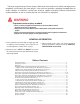
5-04 AS20001, Rev 3 DOING OUR BEST TO PROVIDE YOU THE BEST 55 GALLON LAWN & GARDEN SPRAYER OPERATORS MANUAL READ complete manual CAREFULLY BEFORE attempting operation. ASSEMBLY CALIBRATION OPERATION REPLACEMENT PARTS DEMCO Dethmers Mfg. Co. 4010 320th St. P.O. Box 189 Boyden, IA 51234 PH: (712) 725-2311 Toll Free: 1-800-543-3626 FAX: 1-800-845-6420 www.demco-products.
Thank you for purchasing a Demco sprayer. We feel you have made a wise choice and hope you are completely satisfied with your new sprayer. If you have any questions regarding the applications of certain solutions or chemicals, contact your chemical supplier and follow chemical manufacturer recommendations as well as all licensing and use restrictions or regulations.
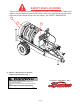
SAFETY SIGN LOCATIONS Types of safety sign and locations on equipment are shown in illustration below. Good safety requires that you familiarize yourself with various safety signs, type of warning, and area or particular function related to that area, that requires your SAFETY AWARENESS. B A B A. AB21014 - Warning: Refer to chemical supplier and manufacturer Qty. 1 WARNING B. AA21012 - Small Demco Qty.
BOLT TORQUE TORQUE DATA FOR STANDARD NUTS, BOLTS, AND CAPSCREWS. Tighten all bolts to torques specified in chart unless otherwise noted. Check tightness of bolts periodically, using bolt chart as guide. Replace hardware with same grade bolt. NOTE: Unless otherwise specified, high-strength Grade 5 hex bolts are used throughout assembly of equipment. Bolt Torque for Standard bolts * Torque Specifications A 1/4 5/16 3/8 7/16 1/2 9/16 5/8 3/4 7/8 1 GRADE 2 lb-ft (N.m) GRADE 5 lb-ft (N.
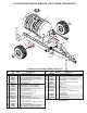
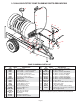
5 GALLON SKID MOUNT SPRAYER WITH TR55CB (TRAILER KIT) 18 3 4 1 17 5 8 14 6 16 7 12 7 2 11 7 9 28 13 9 24 7 19 26 29 7 19 10 7 9 21 7 26 20 19 7 9 22 27 25 23 55 GALLON SPRAYER FRAME PARTS LIST REF. NO. 1. 2. 3. 4. 5. 6. 7. 8. 9. 10. 11. 12. 13. 14. 15. 16. 17. 18. 20. 29. PART QTY. NO. REQD DESCRIPTION 5316 2 50" Strap Assembly 00004 2 5/16î Flatwasher 02802 2 5/16"-18 UNC Nylon Insert Locknut 04352 2 5/16"-18 UNC x 4" F.T. Hex Hd.
1.5 GALLON ELECTRIC PUMP PLUMBING PARTS BREAKDOWN 33 23 22 13 14 16 23 32 14 4 23 17 23 21 29 26 6 27 24 7 25 23 9 23 12 23 18 19 30 20 2 35 1 12 5 11 8 1 10 31 5 34 23 28 3 5 PUMP PLUMBING PARTS LIST REF. PART QTY. NO. NO. REQD DESCRIPTION 1. 00214 6 1/4" Flatwasher 2. 00336 4 1/4"-20 UNC x 1-1/4" Hex Head Bolt 3. 00907 1 3/8"-16 UNC x 1" Hex Head Bolt 4. 00955 1 1/4"-20 UNC x 2" Rd. U-bolt 5. 02772 7 1/4"-20 UNC Nylon Insert Locknut 6. 03900 1 3/8" FPT x 3/8" FPT Valve 7.
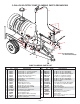
5 GALLON ELECTRIC PUMP PLUMBING PARTS BREAKDOWN 34 20 21 17 16 21 17 33 4 32 21 28 23 12 25 18 30 26 21 21 35 a b d 23 9 22 14 21 6 27 15 31 21 24 14 29 7 1 36 14 22 2 21 1 21 5 8 11 10 13 5 21 14 23 3 NOTE: Use thread sealant on all threaded fittings. 5 PUMP PLUMBING PARTS LIST REF. PART QTY. NO. NO. REQD DESCRIPTION 1. 00214 6 1/4" Flatwasher 2. 00336 4 1/4"-20 UNC x 1-1/4" Hex Head Bolt 3. 00907 1 3/8"-16 UNC x 1" Hex Head Bolt 4. 00955 1 1/4"-20 UNC x 2" Rd.
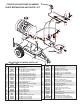
(TR55RP) ROLLER PUMP PLUMBING PARTS BREAKDOWN AND PARTS LIST 20 17 24 28 11 28 19 16 19 2 28 41 18 28 25 18 23 33 21 32 39 33 26 32 34 8 40 18 44 26 32 43 37 15 36 26 22 26 26 30 45 28 31 28 29 39 33 34 32 a 33 b c 38 d 26 33 30 6 5 27 39 34 26 32 10 26 7 3 26 32 35 18 26 4 2 32 13 12 8 1 14 9 R0LLER PUMP PLUMBING PARTS LIST REF. PART QTY. NO. NO. REQD DESCRIPTION 1. 00036 2 5/16" Lockwasher 2. 00214 5 1/4" Flatwasher 3. 00907 1 3/8-16 UNC x 1 Hex Head Bolt 4.
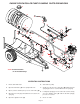
ENGINE DRIVEN ROLLER PUMP PLUMBING PARTS BREAKDOWN 41 40 20 17 24 27 27 44 43 16 19 37 B 11 27 36 26 18 26 45 2 19 31 28 A 30 15 23 39 27 34 32 26 18 18 26 30 C 32 26 30 39 21 33 33 25 22 18 8 26 28 26 a 33 30 13 b 34 c 14 18 32 38 d 5 26 18 3 10 32 10 6 9 26 28 35 D 26 29 30 39 7 1 12 30 4 9 18 33 34 9 26 32 NOTE: Use thread sealant on all threaded fittings. OPERATING INSTRUCTIONS 1. Fill the tank with water. 6. Start and run pump.
ENGINE DRIVEN ROLLER PUMP PLUMBING PARTS LIST REF. PART QTY. NO. NO. REQD DESCRIPTION 1. 00036 2 5/16" Lockwasher 2. 00214 4 1/4" Flatwasher 3. 00372 4 5/16"-18 UNC x 1-1/2" Hex Head Bolt 4. 01872 2 Rubber Bumper 5. 02653-70 1 Pump Drive Shaft Shield 6. 02658-10 1 Engine Mounting Plate 7. 02660-70 1 Pump Mounting Bracket 8. 02772 4 1/4"-20 UNC Nylon Insert Locknut 9. 02802 9 5/16-18 UNC Nylon Insert Locknut 10. 02990 5 5/16-18 UNC x 1 Hex Head Bolt 11. 04055 4 1/4-20 UNC x 1 Hex Head Bolt 12.
ENGINE DRIVEN DIAPHRAGM PUMP PARTS BREAKDOWN NOTE: Use thread sealant on all threaded fittings.
DIAPHRAGM PUMP INSTRUCTIONS OPERATION INSTRUCTIONS MAINTENANCE INSTRUCTIONS 1. Be sure oil is halfway up the clear oil sight tube. If necessary, fill to correct level with 30 weight nondetergent motor oil. 1. After use, flush pump with clean water. 2. Change oil and diaphragms every 500 hours. To drain oil from the pump, remove cap from oil sight tube, turn pump upside down and rotate the shaft until oil stops flowing out.
PISTON PUMP W/ SPRAY GUN PLUMBING PARTS BREAKDOWN 23 5 9 32 38 36 27 13 34 a c b 32 31 24 28 d 27 22 37 7 28 24 29 14 25 17 27 30 1 16 15 35 31 1 28 NOTE: Use thread sealant on all threaded fittings. 10 6 21 22 28 26 20 1 4 19 16 33 2 8 12 3 11 11 18 PISTON PUMP PLUMBING PARTS BREAKDOWN REF. PART QTY. REF. PART QTY. NO. NO. REQD DESCRIPTION NO. NO. REQD DESCRIPTION 23. 23H 1 Spray Gun (less wand & tip) 1.
80" BOOM (80B25) PARTS BREAKDOWN 11 17 12 19 3 8 12 11 49 10 1 17 20 7 8 4 12 18 9 6 80" BOOM (80B25) PARTS LIST REF. PART QTY. NO. NO. REQD DESCRIPTION 1. 00004 4 5/16" Flatwasher 2. 00062 2 1/4"-20 UNC Hex Nut 3. 00068 2 1/4"-20 UNC x 3/4" Hex Bolt 4. 00059 8 3/8" Flatwashers 5. 00337-95 4 1-1/4" Boom Clamp 6. 00909 2 5/16"-18 UNC x 1-1/4" Sq. U-bolt 7. 02253-10 1 Center Boom 8. 02678-95 2 Boom Mounting Plate 9. 02592 4 3/8"-16 UNC Nylon Insert Locknut 10.
12' & 18í BOOM (DB12 & DB18) PARTS BREAKDOWN NOTE: Boom shown below is model DB12 12 foot boom 23 25 4 17 3 10 5 23 15 3 10 23 26 10 24 31 6 30 2 32 22 20 7 19 21 1 11 1 12 8 14 15 18 9 29 23 24 DB12 & DB18 PARTS LIST 23 13 REF. NO. PART NO. QTY.
STANDARD ELECTRIC PUMP (8000 543 150) PARTS BREAKDOWN 2 3 1 4 ELECTRIC PUMP (8000 543 150) PARTS LIST REF. NO. 1. 2. 3. 4. 5. PART NO. 94 382 09 94 378 00 94 391 09 94 395 06 94 385 03 DESCRIPTION Pumphead complete w/viton parts Upper Housing Kit Viton Valve Kit Santoprene Diaphragm Kit Lower Housing Drive assembly 3.0 degree Cam 6. 94 370 03 Motor and Base Assembly Please order replacement parts by PART NO. and DESCRIPTION. 5 6 5 G.P.M. ELECTRIC PUMP (10983) PARTS BREAKDOWN OPT.
ROLLER PUMP PARTS BREAKDOWN CAST IRON C4101 SILVER CAST XL4101 2 11 3 10 9 8 7 13 5 4 3 2 1 6 SILVER CAST ROLLER PUMP PARTS LIST XL4101 CAST IRON ROLLER PUMP PARTS LIST C4101 REF. NO. 1. 2. 3. 4. 5. 6. 7. 8. 9. 10. - PART QTY. NO. REQD DESCRIPTION 0600 1 Name Plate (specify pump model #.
PTO DRIVEN ROLLER PUMP PARTS LIST CAST IRON C6500D SILVER CAST XL6500 2 9 3 10 6 7 8 5 4 3 2 1 CAST IRON ROLLER PUMP PARTS LIST C6500D SILVER CAST ROLLER PUMP PARTS LIST XL6500 REF. NO. PART NO. QTY. REQD 1. 2. 3. 4. 5. 6. 7. 8. 9. 10. - 0600 BAC37 *2107 0002 0200 6600 *1720 0008 *1005 0004 1002 0004 0300 6600 0500 6600 0100 6600 1321 0012 3430 0380 1 2 2 1 1 6 6 1 1 1 1 - DESCRIPTION Name Plate (specify pump model no.
(C5330R ) PISTON PUMP PARTS BREAKDOWN 1 12 2 4 13 3 5 14 B C 15 16 11 D E 10 6 7 A 9 21 18 19 20 17 8 (C5330R ) PISTON PUMP PARTS LIST REF. NO. 1. 2. 3. 4. 5. 6. 7. 8. 9. 10. 11. 12. 13. 14. 15. 16. 17. 18. 19. 20. 21. PART QTY. NO.
DIAPHRAGM PUMP (D19GR) PARTS BREAKDOWN 49 70 76 58 68 72 1 73 74 6 71 75 59 70 63 5 7 77 8 4 3 2 45 52 44 13 24 57 25 18 29 17 14 21 22 40 27 34 37 36 32 39 38 35 26 28 13 15 31 41 43 30 23 64 13 42 51 66 65 61 47 46 50 11 9 54 53 67 12 10 55 56 69 66 68 65 48 13 16 DIAPHRAGM PUMP (D19GR) PARTS LIST REF. NO. 1. 2. 3. 4. 5. 6. 7. 8. 9. 10. 11. 12. 13. 14. 15. 16. 17. 18. 21. 22. 23. 24. 25. 26. 27. 28. 29. 30. 31. 32. 34. 35. 36. 37. 38. 39. 40. 41.
SPRAY WAND PARTS BREAKDOWN 1 2 13 3 45 12 7 6 8 15 17 14 16 23 19 18 20 24 24 25 26 21 22 11 9 10 SPRAY WAND PARTS BREAKDOWN REF. NO. PART NO. 1. 2. 3. 4. 5. 6. 7. 8. 9. 10. 11. 12. 13. 14. 19684 1NYB 17013 1ZP 19818 1ZP 19819SS 19816 *22138 302SS 19815 19810 19805DEL 19806FRP 17703FRP 19820 420SS 17720 420SS 7622INP DESCRIPTION Housing Assembly Screw Screw Washer Spring Retainer Spring Spring Guide Trigger Guide Lock Spring Ring Trigger Lock Trigger Roll Pin Roll Pin #6 Burr REF.
(8460) BYPASS VALVE PARTS BREAKDOWN (8460) BYPASS VALVE PARTS LIST 10 9 8 7 8 6 4 5 3 2 14 1 18 15 13 12 11 REF. NO. 1. * 2. * 3. 4. * 5. 6. 7. 8. 9. 10. * 11. 12. * 13. 14. 15. 16. 17. 18. 16 17 PART NO. DESCRIPTION 8367AL Guide Sleeve, aluminum 8373SS Outside Spring, stainless steel 8374SS Inside Spring, stainless steel 8371AL Spring Retainer, aluminum 8369NY Washer, nylon 8368SS Adjusting Nut, stainless steel 8362AL Bonnet, aluminum 7688ICP Screw, steel cadium plated (4 req'd.
SPRAYER CALIBRATION PROCEDURES NOTE: To avoid wind drift, use lower pressure and higher spray volume. Guidelines For Sprayer Calibration Before calibrating your sprayer, first determine whether each nozzle is delivering at a uniform rate. Place quart jars under all nozzles and watch as they fill up. The level should rise uniformly and take the same time (within 10%) for all nozzles to fill the jars. Replace any nozzle showing a discharge rate different from the others. Calibrating the Sprayer 1. 2. 3. 4.
SPRAYER CHECKLIST: Downtime caused by field breakdowns is costly and time consuming. Many breakdowns can be eliminated by periodic equipment maintenance. By spending time reviewing this checklist before seasonal spraying application time and following proper after-season care, you can save time and money later. ! WARNING: To Prevent Serious Injury Or Death ï Keep hands, feet, and loose clothing away from rotating parts.