
UnVenTed (VenT-Free) Gas FirePlace sysTem VsGF28nTF, VsGF28PTF
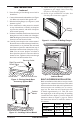
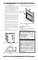
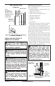
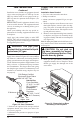
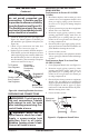
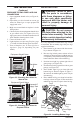
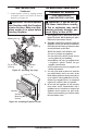
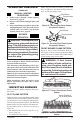
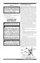
Table Of Contents
- Safety Information
- Local Codes
- Product Identification
- Unpacking
- Product Features
- Air For Combustion and Ventilation
- Installation
- Operating Fireplace
- Inspecting Burners
- Cleaning and Maintenance
- Wiring Diagram
- Specifications
- Troubleshooting
- Replacement Parts
- Technical Service
- Service Hints
- Accessories
- Illustrated Parts Breakdown and Parts List
- Warranty Information

www.desatech.com
119303-01A
19
OPERATING FIREPLACE
Continued
MANUAL LIGHTING
1. Follow steps 1 through 5 under Lighting
Instructions, page 18.
2. Depress control knob and light pilot with
match.
3. Keep control knob pressed in for 30 seconds
after lighting pilot. After 30 seconds, release
control knob. Now follow step 8 under
Lighting Instructions, page 18.
BLOWER
-
Locate the blower switch by opening lower
louver on replace. Blower switch is located at
lower left inside louver door.
This thermostat-controlled blower has a vari-
able speed control with an ON/OFF switch. The
blower will start when the thermostat senses a
sufcient increase in rebox temperature.
Note: It is safe to operate replace with blower
turned off. However, the blower helps distribute
heated air from the replace.
Note: Periodically check the louvers of the
rebox and remove any dust, dirt or other
obstructions.
INSPECTING BURNERS
Check pilot ame pattern and burner ame pat-
terns often.
Figure 29 shows a correct pilot ame pattern. Figure
30 shows an incorrect pilot ame pattern. The incor-
rect pilot ame is not touching the thermocouple.
This will cause the thermocouple to cool. When the
thermocouple cools, the replace will shut down.
If pilot ame pattern is incorrect, as shown in
Figure 30
• turn replace off (see To Turn Off Gas to Ap-
pliance, page 18)
• see Troubleshooting, page 22
Note: The pilot ame on natural gas units will
have a slight curve, but ame should be blue and
have no yellow or orange color.
Figure 29 - Correct Pilot Flame Pattern
(Propane/LP Shown)
Figure 30 - Incorrect Pilot Flame Pattern
(Propane/LP Shown)
Pilot Burner
Thermocouple
Pilot Burner
Thermocouple
Figure 31 shows correct front burner ame pat-
tern. Figure 32 shows incorrect front burner ame
pattern. The incorrect burner ame pattern shows
yellow tipping at top of blue ame.
-
-
CORRECT FLAME PATTERN AT HIGH POSITION
INCORRECT FLAME PATTERN AT HIGH POSITION
Figure 32 - Incorrect Front Burner Flame
Pattern
Figure 31 - Correct Front Burner Flame
Pattern
Yellow Tipping At
Top of Blue Flame
CORRECT FLAME PATTERN AT HIGH POSITION
INCORRECT FLAME PATTERN AT HIGH POSITION