
UnVenTed (VenT-Free) Gas FirePlace sysTem VsGF28nTF, VsGF28PTF


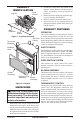
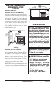


Table Of Contents
- Safety Information
- Local Codes
- Product Identification
- Unpacking
- Product Features
- Air For Combustion and Ventilation
- Installation
- Operating Fireplace
- Inspecting Burners
- Cleaning and Maintenance
- Wiring Diagram
- Specifications
- Troubleshooting
- Replacement Parts
- Technical Service
- Service Hints
- Accessories
- Illustrated Parts Breakdown and Parts List
- Warranty Information

www.desatech.com
119303-01A
9
WARNING: These models have
-
-
currents move heat to wall sur-
smoke, aromatic candles, clean-
Note: Your replace is designed to be used in zero
clearance installations. Wall or framing material
can be placed directly against any exterior surface
on the rear, sides or top of your replace, except
where standoff spacers are integrally attached. If
standoff spacers are attached to your replace,
these spacers can be placed directly against wall
or framing materials.
Use the dimensions shown for rough openings to
create the easiest installation. See Built-In Fire-
place Installation, page 11.
IMPORTANT: Vent-free heaters add moisture to
the air. Although this is benecial, installing re-
place in rooms without enough ventilation air may
cause mildew to form from too much moisture. See
Air for Combustion and Ventilation, page 6.
IMPORTANT: Make sure the replace is level. If
replace is not level, log set will not work properly.
Use the correct gas type (natural or propane/LP)
for your replace. If your gas supply is not cor-
rect, do not install replace. Call dealer where you
bought replace for proper type replace.
This replace has a blower assembly with an
electrical cord. The electrical cord is ve feet in
length. You must locate replace within reach of
120-volt grounded electrical outlet. If not, you
must install an electrical outlet within reach of
replace power cord. The GA3555 outlet acces-
sory may be used for built-in installation when a
blower is installed.
INSTALLING HOOD
Install hood to rail already installed in replace
as shown in Figure 5. Use 3 Phillips screws
provided.
INSTALLATION
Continued
Figure 5 - Installing Hood
Screw
Hood
Rail
ASSEMBLING AND ATTACHING
IMPORTANT: If you are recessing the rebox in
a wall, do not attach trim at this time. See Built-In
Fireplace Installation, page 11.
Note: These instructions are for assembling and
attaching trim to replace.
1. Remove packaging from three pieces of trim.
2. Locate four screws, two adjusting plates
with set screws, and two shims in the hard-
ware packet.
3. Align shim under adjusting plate as shown in
Figure 6, page 10.