READ AND SAVE THESE INSTRUCTIONS INSTALLATION INSTRUCTIONS Model: AC-20452 KENDAL LIGHTING Kendal Lighting (BC) Inc.
1. TOOLS AND MATERIALS REQUIRED Philips screw driver Flat screw driver 11 mm wrench Step ladder Wire cutters 2. PACKAGE CONTENTS c Unpack your fan and check the contents. You should have the following items; a. b. c. d. e. f. g. h. i. j. k. l.
. SAFETY RULES 1. To reduce the risk of electric shock, insure electricity has been turned off at the circuit breaker or fuse box before beginning. 8. Avoid placing objects in the path of the blades. 9. To avoid personal injury or damage to the fan and other items, be cautious when working around or cleaning the fan. 2. All wiring must be in accordance with the National Electrical Code and local electrical codes. Electrical installation should be performed by a qualified licensed electrician. 10.
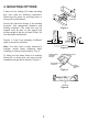
. MOUNTING OPTIONS If there isn't an existing CUL listed mounting box, then read the following instructions. Disconnect the power by removing fuses or turning off circuit breakers. Outlet box Secure the outlet box directly to the building structure. Use appropriate fasteners and building materials. The outlet box and its support must be able to fully support the moving weight of the fan (at least 50 lbs). Do not use plastic outlet boxes.
. HANGING THE FAN Ceiling hanger bracket REMEMBER to turn off the power. Follow the steps below to hang your fan properly: Ceiling canopy Step 1. Remove the decorative canopy bottom cover from the canopy by turning the cover counter clockwise. (Fig. 5) Canopy cover Figure 5 Step 2. Remove the hanger bracket from the canopy by removing the non-slotted screws from the bottom of the mounting bracket and loosening the slotted screw a half turn from the screw head.
. MAKE THE ELECTRIC CONNECTIONS Code switch WARNING: To avoid possible electrical shock, be sure electricity is turned off at the main fuse box before wiring. ON NOTE: This remote control unit is equipped with 16 code combinations to prevent possible interference from or to other remote units. The frequency switches on your receiver and transmitter have been preset at the factory.
Note: Fan must be installed at a maximum distance of 20 feet from the transmitting unit for proper signal transmission between the transmitting unit and the fan's receiving unit. 7. INSTALLATION OF SAFETY SUPPORT Attach the lag bolt and flat washer to ceiling joist. Attach the safety cable to lag bolt. Slide cable clamp onto safety cable (from fan). Place the end of cable through the lag bolt. Pull as much cable through lag bolt as possible.
9. ATTACHING THE FAN BLADES Fasten blade assembly to motor using the flat washers and screws supplied. (Fig. 14) CAUTION: Make tightened securely. sure all screws are Flat washers Blade Screws Figure 14 10. ATTACHING THE MOUNTING PLATE 1. Remove 1 of 3 screws from the mounting ring and loosen the other 2 screws. (Do not remove) 2.
11. ATTACHING THE LIGHT PLATE NOTE: Before starting installation, disconnect the power by turning off the circuit breaker or removing the fuse at fuse box. Turning power off using the fan switch is not sufficient to prevent electric shock. Raise and hold the light plate close to the mounting plate and proceed to do the wire connections, Connect the white wire connectors from the light plate and fan, follow the same procedure with the black wire connectors.
13. INSTALLING THE TRANSMITTER HOLDER Outlet box Switch Wall plate Select a location to install your remote control system transmitter. You can replace an existing wall switch or, install the transmitter on ANY flat surface. Option 1: Install the cremote ontrol system using an existing wall switch outlet box. Make sure the electrical power is TURNED OFF at the main panel before continuing. Figure 18 Step 1. Remove the existing wall plate and the old switch from the wall outlet box.
14. INSTALLING THE BATTERY Remove the back cover on the transmitter and install both, 3 volt (#2032) batteries that were included with the remote control. Make sure the + sign is facing up. (Fig. 21) 15. OPERATING YOUR TRANSMITTER Figure 21 Restore power to ceiling fan and test for proper operation. A. , and buttons: These three buttons are used to set the fan speed as follows: = low speed = medium speed = high speed B. button: This button turns the fan off. C. button: This button controls the light.
16. CARE OF YOUR FAN Here are some suggestions to help you maintain your fan. 1. Because of the fan's natural movement, some connections may become loose. Check the support connections, brackets, and blade attachments twice a year. Make sure they are secure. (It is not necessary to remove fan from ceiling.) 2. Clean your fan periodically to help maintain its new appearance over the years. Use only a soft brush or lint-free cloth to avoid scratching the finish.
17. TROUBLESHOOTING Problem Solution Fan will not start. 1. Check circuit fuses or breakers. 2. Check line wire connections to the fan and switch wire connections in the switch housing. CAUTION: Make sure main power is off. 3. Check to make sure the dip switches from the transmitter and receiver are set to the same frequency. Fan sounds noisy. 1. Make sure all motor housing screws are snug. 2. Make sure the screws that attach the fan blade bracket to the motor hub is tight. 3.