V 1.3 Model 20630 / 20930 Installation Manual For Use On Vehicles With 12 Volt (Negative Ground) Electrical Systems 7955 Cameron Brown Ct. Springfield, Virginia USA 22153 Tel: (703) 866-2000 or (800) 337-4468 www.designtech-intl.
Instructions for First Defense® Alarm Congratulations on your purchase of our First Defense®, the first car alarm designed to protect both You and Your Car. First Defense® Protects Your Car: Transmitter Your First Defense® Transmitter Operates As Follows: The light on the transmitter will turn Green when button #1 is pressed, Red with button #2 and Yellow with button #3 when it is transmitting.
Before You Get Started Installation Instructions Contents: 1 First Defense® siren module 1 3-Button transmitter (comes with long-life lithium battery 2 Blue Scotch-Lock wire connectors 4 Cable ties (4" long) for wires 1 Spare blue 15 amp fuse 1 Ring-terminal for ground connection 2 Screws & lock washers for mounting bracket 2 "Warning: Protected by DesignTech" window decals Step 1 - Mounting the Unit and Connecting the Ground Wire Functions: RED +12 Volts ("+" positive) BLACK Ground ("
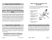
Step 2 - Red +12 Volt Wire How To Use The Scotch-Lock Connector Connect the RED wire with its in-line fuse holder and 15 amp fuse to the +12 volt ("+") side of the battery terminal, using our eyelet connecter. To do so, simply unscrew the battery terminal connector nut and then slip the eyelet over the bolt and retighten the nut. The diagram below shows how to use the blue Scotch-Lock wire connectors to tap into the desired wires. This example is for the parking light connection.
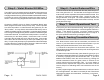
Step 5 - Violet Starter Kill Wire Step 6 - Coaxial Antenna Wire The VIOLET wire is a transistor ground output that is active whenever the system has been armed by the transmitter. This output is used to engage a starter kill relay (optional and not included with this alarm) to prevent the vehicle from starting whenever the alarm system is armed.
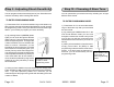
Step 9 - Adjusting Shock Sensitivity Step 10 - Choosing A Siren Tone You can program the shock sensitivity level of your Smart Alarm® to maximize sensitivity while reducing false alarms. You can personalize your alarm's sound by selecting one of eight different siren sounds.
Step 11 - Trying Out the Alarm Now everything is complete and it is time to try out the system. • Press button #3 (yellow) and the headlights should come on. They will turn off in 30 seconds -- or you can turn them off by pressing the YELLOW button again. • Press button #2 (red) for 1-2 seconds to get the CarFinder® feature. The siren will sound for 1-2 seconds and the lights will flash. • Press and hold button #2 (red) for 3 seconds to get the Panic mode.
The alarm is armed and the wireless sensor is triggered, then the alarm will fully activate sound its siren and flashing the lights indicating an intrusion or break in attempt. Sensors must be coded to the alarm module just like a transmitter using the Step 8 of the instructions on page 9. Trouble Shooting DesignTech's Universal Remote Control Garage Door Opener system makes a great add-on to the Smart Alarm®.
LIMITED WARRANTY DesignTech International, Inc. Warrants to the original consumer/purchaser that this product shall be free of defects in material and workmanship under normal use and circumstances for a period of two (2) years from the date of original purchase for use. When the original consumer/purchaser returns the product to DesignTech International Inc., 7955 Cameron Brown Court, Springfield, Virginia 22153, USA within the warranty period, and if the product is defective DesignTech International, Inc.