
User Manual


PREFACE Stackable LCC/LCD Oven Owner’s Manual
4 Version 1.1
Copyright © 2012 by Despatch Industries.
All rights reserved. No part of the contents of this manual may be reproduced, copied or transmitted in any form or by any
means including graphic, electronic, or mechanical methods or photocopying, recording, or information storage and
retrieval systems without the written permission of Despatch Industries, unless for purchaser's personal use.
5.1. Load Oven ............................................................................................................. 36
5.2. Pre-Startup Checklist ............................................................................................. 36
5.3. Operating Procedure ............................................................................................. 37
5.3.1. Start Oven .......................................................................................................... 37
5.3.2. Working with Protocol 3 Operating Modes ........................................................ 38
5.3.3. Operation Sequence when Equipped with Optional Beacon Light .................... 38
5.3.4. Sequence of Operation for Ovens Equipped for Inert Atmosphere Oven ......... 39
5.3.5. Manual Unlock and Main Disconnect ................................................................ 41
5.3.5.1. Manual Unlock ............................................................................................... 41
5.3.5.2. Main Disconnect Switch ................................................................................. 41
5.4. Latch Opening for Models LCC/LCD Models 1-51V or 1-51NV ............................ 41
5.4.1. To Open the LCC/LCD1-52V & 1-51NV Oven Door ......................................... 41
5.4.2. To Close the LCC/LCD1-52V & 1-51NV Oven Door ......................................... 42
6. Maintenance ..................................................................................................................... 43
6.1. Checklist ................................................................................................................ 43
6.2. Lubrication ............................................................................................................. 43
6.3. HEPA Filter Replacement ...................................................................................... 43
7. Troubleshooting: Error Messages and Alarm ................................................................... 44
8. Appendices ....................................................................................................................... 45
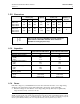
8.1. HEPA Filter Pressure Reading Worksheet ............................................................ 45
8.2. Standard Products Warranty ................................................................................. 46
8.3. Electrical Schematics ............................................................................................. 46
Figures
Figure 1. Stackable LCC/LCD Series Oven. ................................................................................. 15
Figure 2. Protocol 3 Operator Interface. ........................................................................................ 16
Figure 3. This Side Up Graphic. .................................................................................................... 17
Figure 4. Magnehelic Pressure Gauge Measures Pressure in front of the HEPA filter. ............... 20
Figure 5. Door Lock Manual Override Key (LCC/LCD/LLC/LLD). ................................................. 21
Figure 6. LCC/LCD Connections Panel. ........................................................................................ 24
Figure 7. Exhaust Port on the Left Side of the LCC/LCD Oven. ................................................... 27
Figure 8. Open the front panel for access. .................................................................................... 28
Figure 9. Conduit entrance at rear of oven and open front panel. ................................................ 28
Figure 10. Example HEPA Filter (Silicone-free) and Close-Up. .................................................... 30
Figure 11. Remove inner casing to install HEPA filter.................................................................. 31
Figure 12. Install HEPA high-temperature filter. ............................................................................ 32
Figure 13. Install HEPA standard filter. ......................................................................................... 32
Figure 14. Options for starting high-temperature HEPA Filters ..................................................... 34
Figure 15. Power the Oven. ........................................................................................................... 37
Figure 16. Nitrogen Flowmeter. ..................................................................................................... 39
Figure 17. Adjust Nitrogen Maintain Needle Valve. ....................................................................... 40
Figure 18. Water and Nitrogen Piping Schematic. ........................................................................ 40
Figure 19. Press and hold DOOR RELEASE. ............................................................................... 41
Figure 20. Pull handle out away from door. ................................................................................... 42
Figure 21. Oven door latch and door fully open (latch perpendicular to oven door). .................... 42
Figure 22. Door fully close and latch fully engaged. ...................................................................... 42
Figure 23. LCC1-16-4 (Drawing 313930-01). ................................................................................ 47
Figure 24. LCC1-16-4 (Drawing 313930-02). ................................................................................ 47
Figure 25. LCC1-16-4 (Drawing 313930-03). ................................................................................ 47
Figure 26. LCC1-16N-4 (Drawing 313931-01). ............................................................................. 47
Figure 27. LCC1-16N-4 (Drawing 313931-02). ............................................................................. 47
Figure 28. LCC1-16N-4 (Drawing 313931-03). ............................................................................. 47
Figure 29. LCC1-51-4 (Drawing 313932-01). ................................................................................ 47