
Full Product Manual

En.10 DK2 Avalanche man.
ENGLISH
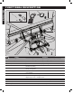
SNOW PLOW ASSEMBLY
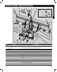
1. Carefully unpack the carton (g.2), accounting for each of the parts by referring
to the function picture, parts list and schematic drawing (see page En.21)
2. Continue to refer to the parts list and exploded drawing while assembling the
plow.
3. Using the grade 8 bolts and nuts included, bolt together the two halves of the
Snow Plow blade (g.3, C
L
and C
R
, below).
4. Attach the scraper (three pieces, a long, S
L,
and two short ones, S
S
; g.4, at left)
to the front lower edge of the full blade using 25 mm (1”) x M10 grade 8 carriage
bolts, 10 mm washers, and M10 Nylock nuts (g.5). The long piece of the
scraper overlaps both halves of the blade. The
shorter piece lls in the rest. The carriage bolts are
inserted so that their domed caps are at the front of
scraper, which lies on the lower front (concave side)
edge of the blade. The nuts screw on from the back
(convex) side of the plow blade. Tighten the nuts.
5. Attach the two skid shoe holders (g.6) to the
bottom of the lower
cross rib on the back
of the plow blade.
They should be attached so that they are cupped
upwards, the ends of the holders with the two
holes angled slightly when the blade stands
vertically and the end having the single large hole
aligned horizontally so that the shoes are vertical.
To attach each, use 2 M12 x 32 mm gr.8 hex
head bolts inserted from below, and 2 M12 Nylock nuts threaded on from the
top to attach it to the cross rib.
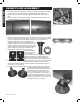
6. If not already done, thread an M18 nut onto the shaft of each skid shoe (g.7).
Assuming the blade assembly is held in a
vertical position, insert the skid shoes into
the skid shoe holders from below. Hold
them in place with a Nylock nut on top of
each (g.8). Temporarily set the shoes so
they hold the blade scraper about 1 cm (1/2
inch) above the surface. This is the normal
setting for paved surfaces, but you can vary
the height according to conditions.