
Manual

There is a limit 0.5 ohm maximum resistance drop per wire over the seperation distance.
AWG Maximum Seperation (feet)
20 50
18 75
16 125
1
4 175
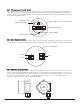
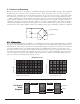
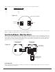
Reference figure 4 for wiring diagram. Also note the jumper that is required on the remote sensor connector board.
Failure to install this jumper will cause a sensor fault condition.
Remote Mounting Configuration - Bridge Voltage Adjustment
When a sensor is remote mounted, consideration must be given to the lengths of cable used and how it affects the
sensor bridge voltage. Differing lengths of cables will have varying amounts of resistance which will shift the sensor
bridge voltage. Because of this, the bridge voltage will need to be adjusted after initial power up. This adjustment is
only required after initial installation and will not be necessary thereafter, even in the event of replacement of the
plug-in sensor. See section 3.6.2 for instructions.
3.6 START UP
Upon completion of all mechanical mounting and termination of all field wiring, apply system power and observe
the following normal conditions:
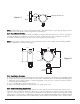
Model FP-524C Combustible Gas Sensor PG.10
WHT
BLK
YEL
BLU
mA
VDC Power In
4-20 mA Output
S
ensor
Base Connector Board
Figure #3
1234
WHT
BLK
YEL
BLU
Install
Jumper
Remote Transmitter
FP-524C-RT
Remote Sensor
FP-524C-RS
Measure Bridge Voltage
From White (1) to Blue (4)
Target voltage is 2.7v
WHT
BLK
YEL
BLU
Plug unused port
with 3/4 NPT plug.
Figure #4