
Manual

Note:
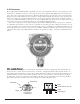
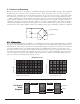
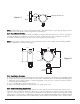
In all installations, the sensor element in SS housing points down relative to grade (Fig. 1). Improper sensor
orientation may result in false reading and premature sensor damage.
3.5.4 Local Electrical Codes
Sensor and transmitter assemblies should be installed in accordance with all local electrical codes. Use appropriate
conduit seals. Drains are required at the bottom of vertical conduit runs. The sensor assemblies are designed to
meet NEC and CSA requirements for Class I; Div. 1; Groups B, C, D, environments.
Note:
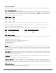
An appropriate conduit seal must be located within 18" of the sensor assembly. Crouse Hinds type EYS2,
EYD2 or equivalent are suitable for this purpose.
3.5.4 Installation Procedure
a) Remove the junction box cover and un-plug the control circuit by grasping the two thumb screws and pulling outward.
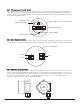
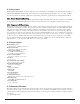
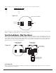
b) Securely mount the sensor junction box in accordance with recommended practice. See dimensional drawing (Fig. 2).
c) Observing correct polarity, terminate 3 conductor field wiring to the sensor base connector board in accordance
with the detail shown in Figure 3.
d) Use a 3/4 NPT plug to block the unused port.
e) Replace the plug-in transmitter circuit and replace the junction box cover.
3.5.5 Remote Mounting Applications
Some sensor mounting applications require that the gas sensor head be remotely mounted away from the sensor
transmitter. This is usually true in instances where the gas sensor head must be mounted in a location that is diffi-
cult to access. Such a location creates problems for maintenance and calibration activities. Detcon provides the FP-
524C sensor in a remote-mount configuration in which the sensor (Model FP-524C-RS) and the transmitter (Model
FP-524C-RT) are provided in their own condulet housing and are interfaced together with a three conductor cable.
Model FP-524C Combustible Gas Sensor PG.9
4 3/4"
3/4" NPT
1/4" Dia.
Mounting Holes
7 1/4"
6 1/8"
5 1/2"
3/4" NPT
Rainshield/
Splashguard
2"
2 1/8"
Figure #2
EYS
S
eal
Fitting
Drain
“T”
Plug any unused ports.
Figure #1