CHAUDIÈRE ÉLECTRIQUE Modèles : HYDRA09-E2401M-D HYDRA15-E2401M-D HYDRA18-E2401M-D HYDRA20-E2401M-D HYDRA24-E2401M-D HYDRA29-E2401M-D DNS C -095 1 Ré v. D INSTALLATEUR / TECHNICIEN : UTILISER LES RENSEIGNEMENTS DANS CE MANUEL POUR L’INSTALLATION ET L’ENTRETIEN DE L’APPAREIL ET GARDER LE DOCUMENT PRÈS DE L’UNITÉ POUR RÉFÉRENCES ULTÉRIEURES. Attention : Ne pas altérer votre unité ou ses contrôles. Appeler un technicien qualifié. PROPRIÉTAIRE : Industries Dettson inc. S.V.P.
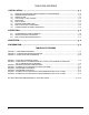
TABLE DES MATIÈRES 1 INSTALLATION ...................................................................................................................... p. 3 1.1) 1.2) 1.3) 1.4) 1.5) 1.6) 1.7) 1.8) 1.9) SIGNALISATION DANGER, MISE EN GARDE ET AVERTISSEMENT..................................................p. 3 REMARQUES IMPORTANTES .................................................................................................................p. 3 RISQUE DE GEL ...............................................
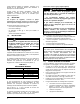
SECTION 1 INSTALLATION 1.1) SIGNALISATION DANGER, MISE EN GARDE ET AVERTISSEMENT Comprenez bien la portée des mots suivant : DANGER, MISE EN GARDE ou AVERTISSEMENT. Ces mots sont associés aux symboles de sécurité. Vous les retrouverez dans le manuel de la façon suivante : DANGER Le mot DANGER indique les plus graves dangers, ceux qui provoqueront la mort ou des dommages corporels et/ou matériels sérieux.
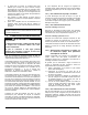
Toutes questions relatives à l’opération, l’entretien ou la garantie de cet équipement doivent être adressées à l’entreprise où l’achat fut effectué. Lorsque toutes les étapes d’installation auront été complétées, remettre ce manuel dans son enveloppe originale et la conserver près de la chaudière pour références ultérieures. 1.5) RÉCEPTION Sur réception de l’appareil, consulter la plaque signalétique de l’appareil. Assurez-vous d’avoir en main la bonne puissance d’appareil ainsi que le bon voltage.
6. 7. 8. Le débit d’eau au travers du système devra être suffisant pour évacuer de façon continue l’énergie développée par la chaudière sinon la protection haute limite désactivera tous les éléments électriques et un fonctionnement à cycles plus ou moins rapprochés des contrôles sera établi (voir le tableau des spécifications techniques, tableau 3, p.
SECTION 2 OPÉRATION 2.1) AJUSTEMENTS ET MISE EN MARCHE FIGURE 1 CARTE ÉLECTRONIQUE HYDRA AVERTISSEMENT La chaudière devra être remplie d’eau et l’air du système éliminé avant de mettre le courant sur l’appareil. Les éléments électriques seront sérieusement endommagés si la chaudière n’est pas pleine d’eau au moment où ils seront mis sous tension. 1. 2. 3. 4. 5.
Contrôle haute-limite mécanique Employer la même procédure tel que mentionné précédemment, cette fois avec l’aquastat mécanique situé au centre à gauche du panneau de contrôle (voir figure 5, p.13, note 3). Les éléments se désengageront tous en même temps. Le contrôle mécanique haute-limite doit être ajusté 20°F au dessus de la température de la carte électronique. Contrôle de modulation Si une sonde extérieure a été installée tel que spécifié au paragraphe 1.9.
SECTION 3 ENTRETIEN Le propriétaire des lieux a les responsabilités suivantes : a. Maintenir en tout temps les environs immédiats de la chaudière libres de tous matériaux combustibles et hautement inflammables ; b. L’air ambiant autour de la chaudière ne devra pas avoir une concentration de poussière et d’humidité excessive ; c. Faire réparer toutes fuites d’eau du système dès leurs apparitions. d. S’assurer que la température ambiante où est installé l’appareil ne dépasse pas 27°C (80°F).
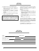
FIGURE 2 VARIATION DE LA TEMPÉRATURE DE L’EAU DE LA CHAUDIÈRE EN FONCTION DE LA TEMPÉRATURE EXTÉRIEURE GRAPHIQUE 1 Plage de variation de la température de l’eau en fonction de l’ajustement du potentiomètre Tmax eau Tmax water 210 Water temperature ( o F) Température de l'eau ( o F) 190 Tmin eau Tmin water 170 150 130 110 90 70 90 110 130 150 170 190 210 Ajustement potentiomètre (o F) Potentiometer setpoint (o F) GRAPHIQUE 2 Variation de la température de l’eau en fonction de la température ex
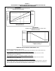
TABLEAU 3 HYDRA - SPÉCIFICATIONS TECHNIQUES TAUX ET PERFORMANCE Puissance (Kw) 9 15 18 20 24 Capacité net (BTU/h) 30 708 51 180 61 416 68 240 81 888 SYSTÈME ÉLECTRIQUE 120 / 240 - 60 - 1 Volts - Hertz - Phase Élément électrique #1 (Kw) 3 5 5 5 4 Élément électrique #2 (Kw) 3 5 5 5 4 Élément électrique #3 (Kw) 3 5 5 5 4 Élément électrique #4 (Kw) N/A N/A 3 5 4 Élément électrique #5 (Kw) N/A N/A N/A N/A 4 Élément électrique #6 (Kw) N/A N/A N/A N/A 4 Consommation (Amp) 38 62 75 83 100 1 Ampérage du circuit (di
FIGURE 3 Identification des composantes 11
FIGURE 4 Schéma type d’une installation à une zone 12
FIGURE 5 Diagramme électrique 13
FIGURE 6 Diagramme en échelle 14
FIGURE 7 Schéma type d’une installation Bi-énergie sans valve 3 voies 15
FIGURE 8 Schéma type d’une installation Bi-énergie avec valve 3 voies 16
COMPOSANTES ET PIÈCES DE REMPLACEMENT 17
LISTE DE PIÈCES HYDRA B50080 Rev.
LISTE DE PIÈCES HYDRA ITEM 1A 1B 1C 2 3 4 5 6 7 8 9 10 11 12 13 14 15 16 17 18 19 20 21 22 23A 23B 23C 24 25 26 27 28 29 30 31 32 33 No DESSIN B20246-03 B20246-02 B20246-01 B20197 B02293-20 B20170-01 B20239 B20245 G11F012 G11Z001 R02L001 B20221-01 B20171-01 R02Z008 L99H010 L99H012 L99H011 A20015 B20179-01 B02293-24 L02G001 L01G007 R02F016 K16012 B20251 B20252 B20253 L99F004 A20024-04 L01H030 A20009-01 A20009-03 R99G006 A20024-01 L05F004 L01H009 L01F009 DESCRIPTION ASSEMBLAGE CHAUDIÈRE ÉLECTRIQUE HYDRA 24
ELECTRIC BOILER Models : HYDRA09-E2401M-D HYDRA15-E2401M-D HYDRA18-E2401M-D HYDRA20-E2401M-D HYDRA24-E2401M-D HYDRA29-E2401M-D DNS C -095 1 Re v. D INSTALLER / SERVICE TECHNICIAN : USE THE INFORMATION IN THIS MANUAL FOR THE INSTALLATION AND SERVICING OF THE UNIT AND KEEP THE DOCUMENT NEAR THE FURNACE FOR FUTURE REFERENCE. Caution : Do not temper with the unit or its controls. Call a qualified service technician. HOMEOWNER : Dettson Industries inc.
TABLE OF CONTENTS 1 INSTALLATION ................................................................................................................. p. 3 1.1) 1.2) 1.3) 1.4) 1.5) 1.6) 1.7) 1.8) 1.9) SAFETY LABELING AND WARNING SIGNS...........................................................................................p. 3 IMPORTANT INFORMATION ....................................................................................................................p. 3 DANGER OF FREEZING .......................
SECTION 1 INSTALLATION 1.1) SAFETY LABELING AND WARNING SIGNS The words DANGER, WARNING and CAUTION are used to identify the levels of seriousness of certain hazards. It is important that you understand their meaning. You will notice these words in the manual as follows : DANGER WARNING Installation and repairs performed by unqualified persons can result in hazards to them and to others. Installations must conform to local codes or, in the absence of same, to codes of the country having jurisdiction.
Upon delivery of the boiler, check the nameplate to be sure that you have received the model with the correct rating and proper voltage. The following items are supplied with the unit: - A pressure relief valve, adjusted to 30 psi; - A drain valve; - A ½" NPT to ⅛" NPT reducer for the installation of an air purge valve; - Modulating outdoor sensor. 1.
6. 7. 8. The flow of water through the system must be sufficient to continuously discharge the energy generated by the boiler. If not, the High Limit protector will disconnect all the electric elements and a more or less frequent cycling mode will be established by the Safety Control (see the Technical Specifications Table, p.
SECTION 2 OPERATION 2.1) ADJUSTMENTS AND START-UP FIGURE 1 HYDRA ELECTRONIC BOARD CAUTION The boiler must be filled with water and all air purged from the system, before turning on the power. If the power is turned on before the boiler is filled with water, the elements will become seriously damaged. 1. 2. 3. 4. 5.
Mechanical High Limit Control Use the same procedure as outlined in the preceding paragraph, but now on the mechanical aquastat, located at the center left of the control panel (see Figure 5. p. 13, note 3). This time the elements will all disengage at the same time. The mechanical limit aquastat must be set 20°F above the temperature on the electronic board. Modulation Control If an outdoor sensor has been installed as specified on page 5, section 1.9.
SECTION 3 MAINTENANCE The property owner has the following responsibilities: a. To maintain the area around the boiler clean at all times and free from combustible and highly flammable material; b. To ensure that the ambient air at the boiler is not excessively dusty or humid; c. To have all water leaks repaired in the system as they arise; d. To ensure that the ambient temperature in the area where the unit is installed does not exceed 27°C (80°F).
FIGURE 2 Boiler water temperature variation according to outdoor temperature GRAPH 1 Range of water temperature variation according to potentiometer adjustment Tmax eau Tmax water 210 Water temperature ( o F) Température de l'eau ( o F) 190 Tmin eau Tmin water 170 150 130 110 90 70 90 110 130 150 170 190 210 Ajustement potentiomètre (o F) Potentiometer setpoint (o F) GRAPH 2 Water temperature variation according to outdoor temperature Tmax eau Tmax water Tmin eau Tmin water -15 -10 -5 0
TABLE 3 HYDRA – TECHNICAL SPECIFICATIONS RATING AND PERFORMANCE Power (Kw) Net capacity (BTU/h) ELECTRICAL SYSTEM Volts - Hertz - Phase Electrical element #1 (Kw) Electrical element #2 (Kw) Electrical element #3 (Kw) Electrical element #4 (Kw) Electrical element #5 (Kw) Electrical element #6 (Kw) Consumption (Amp) Minimum circuit ampacity (wire sizing) 1 Maximum recommended circuit breaker / fuse (Amp) 1 GENERAL INFORMATION Supply - Return Minimum water flow USG/min (L/min.
FIGURE 3 Component Identification 11
FIGURE 4 Typical Diagram of a Single Zone Installation 12
FIGURE 5 Electrical Diagram 13
FIGURE 6 Ladder Diagram 14
FIGURE 7 Typical Diagram of a Dual-Energy Installation without 3-way Valve 15
FIGURE 8 Typical Diagram of a Dual-Energy Installation with 3-way Valve 16
COMPONENTS AND REPLACEMENT PARTS 17
PARTS LIST HYDRA B50080 Rev.
PARTS LIST HYDRA ITEM No DESSIN DESCRIPTION 1A 1B 1C 2 3 4 5 6 7 8 9 10 11 12 13 14 15 16 17 18 19 20 21 22 23A 23B 23C 24 25 26 27 28 29 30 31 32 33 B20246-03 B20246-02 B20246-01 B20197 B02293-20 B20170-01 B20239 B20245 G11F012 G11Z001 R02L001 B20221-01 B20171-01 R02Z008 L99H010 L99H012 L99H011 A20015 B20179-01 B02293-24 L02G001 L01G007 R02F016 K16012 B20251 B20252 B20253 L99F004 A20024-04 L01H030 A20009-01 A20009-03 R99G006 A20024-01 L05F004 L01H009 L01F009 ELECTRIC BOILER ASSEMBLY HYDRA 24 ELECTRIC