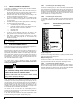
Installation Instructions and Homeowner’s Manual ELECTRIC BOILER ELECTRONIC CONTROL Models: HYDRAR15-E2401M HYDRAR18-E2401M HYDRAR20-E2401M HYDRAR24-E2401M HYDRAR27-E2401M HYDRAR29-E2401M Manufactured by: Dettson Industries Inc C 3400, Industrial Boulevard Sherbrooke, Qc, Canada, J1L 1V8 www.dettson.ca Attention Do not tamper with the unit or its controls. Call a qualified service technician.
TABLE DES MATIÈRES SECTION 1 INSTALLATION .................................... 3 1.1 1.2 DANGER, WARNING AND CAUTION .................. 3 HEATING WITH HOT WATER .............................. 3 1.3 DELIVERY ............................................................. 3 1.4 INSTALLATION ..................................................... 3 1.4.1 1.5 Positioning.............................................................. 3 CLEARANCES ...................................................... 4 1.
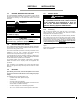
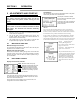
SECTION 1 1.1 INSTALLATION 1.4 DANGER, WARNING AND CAUTION The words DANGER, WARNING and CAUTION are used to identify the levels of seriousness of certain hazards. It is important that you understand their meaning.
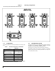
Figure 1: Mounting configurations *The arrows represent the direction of the water flow 1.5 1.6 CLEARANCES The following clearances should be provided for the servicing of the unit: Table 1. Top (access to elements) Sides Bottom Front* Back The proper functioning of your heating system is directly related to the quality of the plumbing installation. Therefore, the entire installation must be performed by qualified technicians.
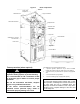
Figure 2: Drain Valve, if required ¼" Boiler components Element High Limit Sensor Water Sensor T° Thermodisc Protector Relay Element Rectifier Card Manometer High Limit Circuit Breaker 208/240VAC – 24VAC Transformator Power Card Regulator Terminal Block Freeze protection (when required) All installations must include the following items: WARNING a.
1.7 1.8.1 INSTALLATION OF THE BOILER Connect the circulating pump on 120V connections points identified N for neutral and P for controlled 120V output in the control panel as shown in Figure 2. The electronic control is designed to operate the circulator on thermostat demand, with a heat purge delay at the end of heating cycle or continuous flow. Refer to the electronic control section to learn how to configure this function. At the time of installation, the following steps should be followed.
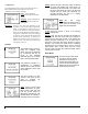
SECTION 2 OPERATION Consumption: 2 ADJUSTMENTS AND START-UP The consumption menu shows an approximated value of the power consumed by the boiler since it was last reset. CAUTION Consumption is written in kilowatt hour and time since last reset is given in hours or in days. The boiler must be filled with water and all air purged from the system, before turning on the power. As shown on the screen, pressing the central button will reset the time and power consumed.
Pump: Choose the way to drive the pump. Off means the pump will activate only when there is a demand from the thermostat. “On” means that the pump will always be active. 20 Seconds indicate that the pump will deactivate 20 seconds following the end of a heating demand from the thermostat. Configuration: The configuration menu’s purpose is to allow the user to adjust settings linked to the interface, such as the temperature’s units and the language.
Figure 4: NAVIGATION IN MENUS 9
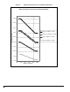
Figure 5: MODULATION IN FUNCTION OF THE EXTERIOR TEMPERATURE Boiler temperature in function of outside temperature 175,0 165,0 155,0 Plinth (T_Setpoint = 175ºF) Boiler temperature (ºF) 145,0 Cast Iron (T_Setpoint = 150ºF) 135,0 Light (T_Setpoint = 125ºF) Mass (T_Setpoint = 100ºF) 125,0 115,0 105,0 95,0 85,0 5,0 15,0 25,0 35,0 45,0 Outdoor air temp (ºF) 10 55,0
3 SECTION - MAINTENANCE It is recommended that the boiler be purged annually, in order to eliminate sediment and sludge that may have accumulated at the bottom of the boiler and covered the heating elements. The property owner has the following responsibilities: a. To maintain the area around the boiler clean at all times and free from combustible and highly flammable material; b. To ensure that the ambient air at the boiler is not excessively dusty or humid; Procedure: 1.
Electric element #1 (kW) Electric element #2 (kW) Electric element #3 (kW) Electric element #4 (kW) Electric element #5 (kW) Electric element #6 (kW) Consumption (Amp @208V / @240V) HYDRAR15-E2401MA 15 11,3 5 5 5 NA NA NA 54 / 62 HYDRAR18-E2401MA 18 13,5 4 5 4 5 NA NA 65 / 75 HYDRAR20-E2401MA 20 15,0 5 5 5 5 NA NA 72 / 83 HYDRAR24-E2401MA 24 18,0 4 5 5 5 5 NA 86 / 100 HYDRAR27-E2401MA 27 20,3 4 4 5 4 5 5 97 / 112 HYDRAR29-E2401MA 29 21,8 4 5 5 5 5 5 104 / 120 In all cases, refer to applicable local
Figure 6: Boiler Dimensions 13
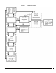
Figure 7: Figure 8: Typical Diagram of a Single Zone Installation Multi-zone Diagram with more than one Circulator 14
Figure 9: Multi-zone diagram with Motorized Valves Figure 10: Dual-energy installation 15
Figure 11: Electrical Diagram 16
6 SECTION - REMPLACEMENT PARTS Figure 12: Exploded Vue (3-4 elements) 17
Table 3.
Figure 13: Exploded Vue (5-6 elements) 19
Table 4.