
Instruction manual


5
English
5
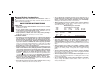
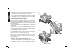
1. To set the saw for a bevel cut, raise the lever to loosen the Bevel
Adjustment.
2. Tilt the shoe to the desired angle by aligning the pointer with the
desired angle mark on the pivot bracket.
3. Retighten the bevel adjustment by lowering the lever.
BEVEL DETENT
DISCONNECT THE SAW FROM POWER SUPPLY
The saw is equipped with a Bevel Detent feature. As you tilt the
shoe you will hear a click and feel the shoe stop at both 22.5 and 45
degrees. If either of these is the desired angle, retighten the lever by
lowering it. If you desire another angle, continue tilting shoe until the
pointer aligns with the desired mark.
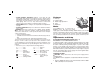
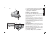
KERF INDICATOR (FIG. 8)
The front of the saw shoe has a kerf indicator for vertical and bevel
cutting. This indicator enables you to guide the saw along cutting lines
penciled on the material being cut. The indicator lines up with the left
(inner) side of the saw blade, which makes the slot or “kerf” cut by
the moving blade fall to the right of the indicator. The ribs on the front
of the shoe are at 1/4” (6.35 mm) spacing. The notches on the front of
the shoe are at 1/2” (13 mm) intervals.
OPERATION
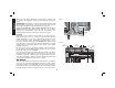
SWITCH (DETAIL PAGE 4)
Pull the trigger switch to turn the motor ON. Releasing the trigger turns
the motor OFF. This tool has no provision to lock the switch in the ON
position, and should never be locked ON in any way.
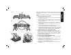
WORKPIECE SUPPORT
Figure 10 and 12 show proper sawing position. Figure 11 and 13
show an unsafe condition. Hands should be kept away from cutting
area, and power cord is positioned clear of the cutting area so that it
will not get caught or hung up on the work.
To avoid kickback, DO support board or panel NEAR the cut,
(Figure 10 &12). DON’T support board or panel away from the cut
FIG. 5
FIG. 6
FIG. 4
B
LOOSEN
TIGHTEN
A