
Use and Care Manual


ENGLISH
6
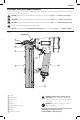
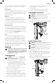
Adjusting Depth (Fig. D)
WARNING: To reduce risk of serious injury from
accidental actuation when attempting to adjust
depth, ALWAYS:
• Disconnect the tool from the airsupply.
• Avoid contact with trigger duringadjustments.
The fastener depth control adjustment feature provides
control of the fastener drive depth from flush with or just
above the work surface to shallow or deepcountersink.
1. Loosen depth adjustment screw
6
with 4 mm hexkey.
2. Move sliding shoe
7
down (away from magazine) to
decrease the drive depth or up (toward the magazine)
to increase the drivedepth.
3. Tighten screw with 4 mm hexkey.
Fig. D
6
7
Actuating Tool
WARNING: To reduce the risk of injury, Always wear
proper eye [ANSI Z87.1 (CAN/CSA Z94.3)] and hearing
protection [ANSI S12.6 (S3.19)] when operating
thistool.
The tool can be actuated using one of two modes:
sequential trip mode and contact tripmode.
Sequential Trip Operation (Fig. A)
The sequential trip mode gets its name from the “sequence”
required to drive a fastener. To drive a fastener, the operator
must first depress the “trip” FULLY against the work surface
and then pull the trigger. To drive a second fastener, the
operator must lift the tool from the work surface, release the
trigger and then repeat the abovesequence.
• The Sequential Trip mode offers a positive safety
advantage since it will not accidentally drive a fastener
if the tool is bumped against any surface or anybody
while the operator is holding the tools with the
triggerpulled.
• The Sequential Trip mode allows “place nailing”
without the possibility of driving a second, unwanted
fastener on recoil as described below under Contact
TripOperation.
Contact Trip Operation (Fig. A)
To drive a fastener, the “trip” and the trigger must both be
depressed. In conventional contact trip tools, the trigger
may be depressed and held, and each “contact” between
the trip and the work surface will drive afastener.
• Single Fastener Placement (Place Fastening): First
position the “trip” FULLY on the work surface, WITHOUT
PULLING THE TRIGGER. Depress the “trip” FULLY until
the nose of the tool touches the work surface and then
pull the trigger to drive a fastener. Do not press the tool
against the work surface with extra force. Instead, allow
the tool to recoil off the work surface to avoid a second
unwantedfastener.
NOTE: Remove your finger from the trigger after
eachoperation.
• Rapid Fire Operation (“Bump” Fastening): First,
hold the tool with the “trip” pointing towards but not
touching the work surface. Pull the trigger and then
tap or “bump” the trip against the work surface using
a bouncing motion. Each depression of the “trip” will
cause a fastener to bedriven.
WARNING: Do not keep trigger pulled when tool is
not inuse.
Clearing a Jam (Fig. E, F)
WARNING: Always disconnect air supply before
clearing a jammedfastener.
On occasion fasteners can jam in the nose of a pneumatic
stapler. This can be caused by striking a metal plate in
the wall, drywall screw, or some other hard object. The
DW451S2 stapler features open drive channel architecture
for jam clearing. To clear a jam follow this procedure:
1. Disconnect the tool from the airsupply.
2. Release the pusher so it is no longer applying force to
thestaples.
3. Open the jam clearing nose door
11
by pulling up on
the tool free jam release
9
.
9
Fig. E
11
Fig. F
4. Remove the jammed fastener. In certain circumstances,
pliers may be required to remove thefastener.
5. Close the tool free jamrelease.
6. Release nail pusher back behindstaples.