
User Guide

Power Budgeting is a new feature, introduced in
the PCI Express Specification, that provides a
mechanism to enable a system to negotiate power
consumption requirements for add-in devices.
Per PCI Express Card Electromechanical
Specification Revision 1.0a or higher, a x1 add-in
card can draw no more than 10W in a x1 slot
unless the board’s required power is successfully
negotiated and allocated by the system (power
budgeting). However, implementation of power
budgeting by a vendor's system is not a compliance
requirement per the PCI Express Card
Electromechanical Specification Revision 1.0a or
higher. Therefore, some chassis may not support
this feature. Power Budgeting jumper P10 is
designed to ensure proper configuration of the
product.
The DM/V600BTEPEQ Media board must be
installed in a slot that can be allocated 25W.
If Power Budgeting is not implemented by a
vendor's system, the DM/V600BTEPEQ Media board
must be plugged into a x4 or higher slot with the
P10 jumper in position 1-2 (power budgeting
ignored). This is allowed per PCI Express Card
Electromechanical Specification Revision 1.0a or
higher because a x4 or greater slot must be able to
support a minimum of 25W.
If Power Budgeting is implemented by a vendor's
system, the DM/V600BTEPEQ Media board can be
plugged into a x1 slot but the P10 jumper must be
in position pins 2-3 (power budgeting adhered to).
WARNING! Installing the DM/V600BTEPEQ
Media board in a x1 slot with the P10 jumper
in position 1-2 will void the warranty of the
DM/V600BTEPEQ Media board.
If the DM/V600BTEPEQ Media board will be
connected to other telephony boards via a CT Bus
cable, you should install the boards to minimize
unused connectors on the CT Bus cable (in addition
to ensuring that the power requirements are met):
■
Install boards in adjacent slots whenever
possible.
■
If the DM/V600BTEPEQ Media board will be
connected to one or more PCI boards, use the
PCI Express slot(s) closest to the PCI slots.
5. Installing the Board
WARNING! Unplug the equipment before
performing the procedures described here.
Failure to disconnect the power before you
open the chassis can result in personal injury.
Ensure that the system is disconnected from
its power source and from all
telecommunications links, networks, or
modem lines whenever the chassis cover is
removed. Do not operate the system with the
cover removed.
CAUTION: To avoid possible damage to the board,
remove power from the computer before beginning
installation. Observe proper anti-static precautions
at all times while handling and installing the board.
To install the DM/V600BTEPEQ Media board,
perform the following steps:
1. Turn off all power to the system and disconnect
the system’s power cords.
2. Remove the computer’s cover.
3. Choose an empty PCI Express expansion slot
and remove the slot’s retaining screw and
access cover plate.
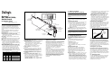
4. Insert the board’s edge connector into the bus
slot, and apply firm pressure to the top edge of
the board until the board is fully seated in the
edge connector.
5. Reinstall the retaining screw.
6. Repeat Step 3 through Step 5 for any additional
boards you are installing.
7. Connect the telephony boards together with a
CT Bus cable of the appropriate size (not
included). If possible, use a cable assembly that
matches the number of boards in your system.
If the cable has more than one unused
connector, install the cable so that all the
unused connectors are at one end of the cable.
PCI Slots
PCI Express
Slots
PCI Express
Board
Computer
Chassis
Remove
Cover
Plate
8. Replace the computer’s cover.
9. Reconnect the computer’s power cord.
6. Connecting to External
Equipment
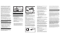
Each RJ-48C jack on the rear bracket of the DM/
V600BTEPEQ Media board supports a single T1 or
E1 digital network interface. Use an appropriate
cable to connect each RJ-48C jack on the bracket
to your CSU or other network termination
equipment.
The following figure illustrates the pinout of the RJ-
48C jack.
7. After Installing the Board
The DM/V600BTEPEQ Media board requires the use
of a Dialogic
®
System Software version that
specifically supports it.
If this is the first Dialogic
®
telecom board you have
installed in your system, you will need to install an
appropriate version of the Dialogic
®
System
Software and configure the software for the specific
board(s) you are using. Refer to the installation
and configuration documentation that accompanies
the release for instructions.
If you are installing the DM/V600BTEPEQ Media
board in a system that already has the Dialogic
®
System Software installed, you should verify that
your installed software version supports the board.
If not, you will need to obtain and install a Service
Update that does support the DM/V600BTEPEQ
Note:
Your CT Bus cable may
have a different number of
connectors (drops).
CT Bus
Cable
Colored
Stripe
(Pin 1)
Media board before configuring the system for the
newly installed board(s).
Please refer to the Release Update document for
your release version (on the Dialogic Telecom
Support Resources web page) for up-to-date
information about support for PCI Express boards
and any known issues relating to their use.
For technical specifications and product information
go to: http://www.dialogic.com/products.htm.
8. Removing the Board
Removal of the DM/V600BTEPEQ Media board is
essentially the reverse of the installation
procedure:
1. Observe anti-static precautions.
2. Disconnect the telephony cables.
3. Remove the computer’s power cord.
4. Remove the computer’s cover.
5. Disconnect the CT Bus cable (if applicable).
6. Remove and set aside the board’s retaining
screw.
7. Remove the board and place it in static-
protective packaging.
9. Warranty and Return Information
Warranty Period
For specific warranty information for this board,
refer to the Warranty section of the Products page,
located at this URL: http://www.dialogic.com/
warranties/.
Contacting Technical Support
Dialogic provides technical support for its products
through a network of value added distributors who
are trained to answer technical questions on
installing and configuring Dialogic® products. If
you are unsure how to contact your support
channel, please call Dialogic in the United States at
973-967-6600 (9am-5pm EST) and we will assist in
obtaining the appropriate support channel.
Outside the United States please refer to http://
www.dialogic.com/support/contact to obtain local
contact information. Dialogic also provides direct
support via Dialogic
®
Pro™ Services agreements.
For more details of direct support from Dialogic
please refer to:http://www.dialogic.com/support/
Dialogic Pro
Returning a Product
To return a board for warranty repair or any other
returns, please refer to the following: http://
www.dialogic.com/support/hwfaults.
10. Sales Assistance
If you have a sales question, please contact your
local Sales Representative or the Regional Sales
Office for your area. Address, telephone and fax
numbers, are available at the Dialogic website
located at: http://www.dialogic.com/contact.htm.
To purchase Dialogic® products, please refer to the
following website to locate the appropriate
supplier: http://www.dialogic.com/purchase.htm.
All contents of this document are furnished for informational use
only and are subject to change without notice and do not represent
a commitment on the part of Dialogic Corporation or its subsidiaries
(“Dialogic”). Reasonable effort is made to ensure the accuracy of the
information contained in the document. However, Dialogic does not
warrant the accuracy of this information and cannot accept
responsibility for errors, inaccuracies or omissions that may be
contained in this document.
INFORMATION IN THIS DOCUMENT IS PROVIDED IN CONNECTION
WITH DIALOGIC® PRODUCTS. NO LICENSE, EXPRESS OR IMPLIED,
BY ESTOPPEL OR OTHERWISE, TO ANY INTELLECTUAL PROPERTY
RIGHTS IS GRANTED BY THIS DOCUMENT. EXCEPT AS PROVIDED IN
A SIGNED AGREEMENT BETWEEN YOU AND DIALOGIC, DIALOGIC
ASSUMES NO LIABILITY WHATSOEVER, AND DIALOGIC DISCLAIMS
ANY EXPRESS OR IMPLIED WARRANTY, RELATING TO SALE AND/OR
USE OF DIALOGIC PRODUCTS INCLUDING LIABILITY OR
WARRANTIES RELATING TO FITNESS FOR A PARTICULAR PURPOSE,
MERCHANTABILITY, OR INFRINGEMENT OF ANY INTELLECTUAL
PROPERTY RIGHT OF A THIRD PARTY.
Dialogic products are not intended for use in medical, life saving, life
sustaining, critical control or safety systems, or in nuclear facility
applications.
It is possible that the use or implementation of any one of the
concepts, applications, or ideas described in this document, in
marketing collateral produced by or on web pages maintained by
Dialogic may infringe one or more patents or other intellectual
property rights owned by third parties. Dialogic does not provide any
intellectual property licenses with the sale of Dialogic products other
than a license to use such product in accordance with intellectual
property owned or validly licensed by Dialogic and no such licenses
are provided except pursuant to a signed agreement with Dialogic.
More detailed information about such intellectual property is
available from Dialogic’s legal department at 9800 Cavendish Blvd.,
5th Floor, Montreal, Quebec, Canada H4M 2V9. Dialogic
encourages all users of its products to procure all necessary
intellectual property licenses required to implement any
concepts or applications and does not condone or encourage
any intellectual property infringement and disclaims any
responsibility related thereto. These intellectual property
licenses may differ from country to country and it is the
responsibility of those who develop the concepts or
applications to be aware of and comply with different
national license requirements.
Dialogic, Diva, Eicon, Eicon Networks, Eiconcard, Dialogic Pro and
SIPcontrol, among others, are either registered trademarks or
trademarks of Dialogic. Dialogic's trademarks may be used publicly
only with permission from Dialogic. Such permission may only be
granted by Dialogic’s legal department at 9800 Cavendish Blvd., 5th
Floor, Montreal, Quebec, Canada H4M 2V9. Any authorized use of
Dialogic's trademarks will be subject to full respect of the trademark
guidelines published by Dialogic from time to time and any use of
Dialogic’s trademarks requires proper acknowledgement. The names
of actual companies and products mentioned herein are the
trademarks of their respective owners.
Network Interface
Cable Connector
RCV_RING
RCV_TIP
Chassis Ground
XMIT_RING
XMIT_TIP
Chassis Ground
Chassis Ground
Chassis Ground
1
2
3
4
5
6
7
8
1
2
3
4
5
6
7
8
Pinout for RJ–48C Jacks on
PCI Express Board's Bracket
Pin 1