
Installation guide


Dialogic Corporation © 1998-2008
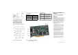
Figure 2. ALS and DID Connector Pinouts
Understanding LED Signals
LEDs on the Mounting Bracket
The LEDs on the mounting bracket provide
information about the status of the different systems
on the board. To identify and locate these LEDs, see
Figure 3.
Figure 3. End Panel Connector and LEDs
Table 2 and Table 3 describe how the end panel LEDs
provide information.
Figure 4. Dialogic® Brooktrout® TR1034 DID/DID &
Loop Start PCI Fax Board
Table 3: Board Status LED
Using the TR1034 DID/DID & Loop
Start Board
Once you have installed your TR1034 Fax Board, install
and configure your fax or voice software application
according to instructions included with the software.
Getting Help
Dialogic provides technical support for customers who have
purchased hardware or software products from Dialogic. If
you purchased products from a reseller, please contact that
reseller for technical support. This equipment contains no
user serviceable parts and is not intended for repair by
unauthorized personnel. If you experience problems with
your board, please use web site below for repair or warranty
information. If the equipment is causing harm to the
telephone network, the telephone company might request
that you disconnect the equipment until the problem is
resolved. www.dialogic.com/support
Copyright and Legal Notice
Copyright © 2006-2008] Dialogic Corporation. All Rights Reserved. You may not
reproduce this document in whole or in part without permission in writing from Dialogic
Corporation at the address provided below.
All contents of this document are subject to change without notice and do not represent a
commitment on the part of Dialogic Corporation or its subsidiaries. Reasonable effort is
made to ensure the accuracy of the information contained in the document. However, due
to ongoing product improvements and revisions, Dialogic Corporation and its subsidiaries
do not warrant the accuracy of this information and cannot accept responsibility for errors
or omissions that may be contained in this document.
INFORMATION IN THIS DOCUMENT IS PROVIDED IN CONNECTION WITH
DIALOGIC® PRODUCTS. NO LICENSE, EXPRESS OR IMPLIED, BY ESTOPPEL OR
OTHERWISE, TO ANY INTELLECTUAL PROPERTY RIGHTS IS GRANTED BY THIS
DOCUMENT. EXCEPT AS EXPLICITLY SET FORTH BELOW OR AS PROVIDED IN A
SIGNED AGREEMENT BETWEEN YOU AND DIALOGIC, DIALOGIC ASSUMES NO
LIABILITY WHATSOEVER, AND DIALOGIC DISCLAIMS ANY EXPRESS OR IMPLIED
WARRANTY, RELATING TO SALE AND/OR USE OF DIALOGIC PRODUCTS
INCLUDING LIABILITY OR WARRANTIES RELATING TO FITNESS FOR A
PARTICULAR PURPOSE, MERCHANTABILITY, OR INFRINGEMENT OF ANY
INTELLECTUAL PROPERTY RIGHT OF A THIRD PARTY.
Dialogic products are not intended for use in medical, life saving, life sustaining, critical
control or safety systems, or in nuclear facility applications.
It is possible that the use or implementation of any one of the concepts, applications, or
ideas described in this document, in marketing collateral produced by or on web pages
maintained by Dialogic Corporation or its subsidiaries may infringe one or more patents or
other intellectual property rights owned by third parties. Dialogic Corporation or its
subsidiaries do not provide any intellectual property licenses with the sale of Dialogic
products other than a license to use such product in accordance with intellectual property
owned or validly licensed by Dialogic Corporation or its subsidiaries. More detailed
information about such intellectual property is available from Dialogic Corporation's legal
department at 9800 Cavendish Blvd., 5th Floor, Montreal, Quebec, Canada H4M 2V9.
The software referred to in this document is provided under a Software License
Agreement. Refer to the Software License Agreement for complete details governing the
use of the software.
Dialogic, Dialogic Pro, Brooktrout, Cantata, SnowShore, Eicon, Eicon Networks,
Eiconcard, Diva, SIPcontrol, Diva ISDN, TruFax, Realblocs, Realcomm 100, NetAccess,
Instant ISDN, TRXStream, Exnet, Exnet Connect, EXS, ExchangePlus VSE, Switchkit,
N20, Powering The Service-Ready Network, Vantage, Connecting People to Information,
Connecting to Growth and Shiva, among others as well as related logos, are either
registered trademarks or trademarks of Dialogic.
Port A Port B
No connection No connection
No connection No connection
Tip 1 Tip 3
Ring 0 Ring 2
Tip 0 Tip 2
Ring 1 Ring 3
No connection No connection
No connection No connection
Port A = ALS or DID Port B = DID only
Connector A
Connector B
Channel
LEDs
Board
Status LED
2 ALS and
2 DID
or 4 DID
1 ALS and
1 DID
2 ALS or
2 DID
Table 2: Channel LEDs
Channel LEDs Meaning
Off Channel is on hook
(inactive).
Flashing at 0.5 second rate Channel is off hook
(active).
Flashing at Ring Cadence
(varies by country)
Incoming ring signal
(ALS only).
PCI Connector
Board
Status LED
Channel LEDs
RJ-45
Connector A
Connector B
RJ-45
Board Status LED Meaning
Flashing yellow
(1.5 second rate)
Board has successfully powered
up and is ready for firmware.
Solid red Board has failed power up tests.
Flashing yellow
and green
Application is downloading
firmware to the board.
Flashing green
(1 second rate)
Firmware is downloaded, and the
board is in service.
Off Board is not powered up.
Module Number
Switch (SW-1)