
- Diamond Systems Corporation User Manual


Diamond-MM-48-AT User Manual V1.01 Page 15
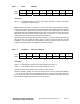
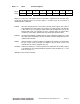
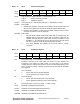
Base + 7 Write D/A Channel and Control Register
Bit No. 7 6 5 4 3 2 1 0
Name DAUPDT DACH2 DACH1 DACH0
DAUPDT Writing a 1 to this bit updates the D/A chip. All channels with new data written to
them since the previous update are updated simultaneously. When a 1 is written
to this bit the other bits in the register are ignored.
When DAUPDT = 0, the remaining bits in this register behave as described below:
DACH2-0 D/A channel number, valid range 0-7
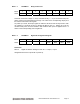
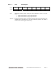
Base + 7 Read Optocoupler Input Port and Edge Detection Register
Bit No. 7 6 5 4 3 2 1 0
Name OEDGE3 OEDGE2 OEDGE1 OEDGE0 OPTO3 OPTO2 OPTO1 OPTO0
OEDGE3-0 Indicates whether an edge has occurred on the indicated digital input line.
1 edge has occurred since last flip flop reset
0 edge has not occurred since last flip flop reset
These bits are reset when this register is read or when the digital input interrupt flip flop is
reset by writing to the CLRO bit in register 8.
OPTO3-0 These signals correspond to the logic state of the optocoupler inputs on J4.