DC-530 Counting Scale Version 2.
Contents 1.0 Introduction.................................................................................................................................. 1 1.1 Capacities and Resolutions . . . . . . . . . . . . . . . . . . . . . . . . . . . . . . . . . . . . . . . . . . . . . . . . . . . . . . . . 1 1.2 Modes of Operation . . . . . . . . . . . . . . . . . . . . . . . . . . . . . . . . . . . . . . . . . . . . . . . . . . . . . . . . . . . . . . 2 1.3 Keyboard and Display . . . . . . . . . . . . . . . . .
5.9 Sample, Count and Print a Label . . . . . . . . . . . . . . . . . . . . . . . . . . . . . . . . . . . . . . . . . . . . . . . . . . . 35 5.10 Scan ID Bar Code, Count and Print a Label . . . . . . . . . . . . . . . . . . . . . . . . . . . . . . . . . . . . . . . . . . 36 6.0 Scale Programming ................................................................................................................... 37 6.1 Programming a New Item Code (Item Registration) . . . . . . . . . . . . . . . . . . . . .
About This Manual This manual contains operating procedures for the DC-530 counting scale and provides the user with all the information necessary for its setup and operation. It is organized based on the procedures you will likely follow when setting up and using your counting scale. This manual applies to Version 2.01 of the DC-530 counting scale series. #AUTION Some procedures described in this manual require work inside the scale base.
1.2 Modes of Operation The DC-530 has four modes of operation that are accessed from the MODE key: • Counting Mode – where all weighing, counting and printing operations take place. • Program Mode – where item data can be programmed into the memory of the scale and edited. • Date & Time where you can set the date and time used in printing on labels and reports. • Set Point Setting where you can program general set points. 1.
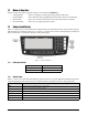
1.3.3 Display Elements The DC-530’s display shows different elements depending on whether it is in “Normal Counting Mode” or “TEP (Teraoka Error Prediction) Counting Mode”. Figure 1-2. Normal Counting Mode Display Elements Figure 1-3.
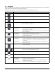
1.3.4 Key Functions The DC-530 features many functions for managing item information and scale operation. Table 1-4 lists the keys and key functions of the DC-530 keyboard and keypad. Some keys have different functions depending on what mode or function you are in. Key Description ON/OFF - Turns the scale display on or off. REZERO key - Used to reset the weight display to zero. SCALE key - Used to select between Scale 1 and Scale 2 if an external scale is connected.
Key Description UNIT WEIGHT key Counting Mode Program Mode - Used to set the Unit Weight. Used to register an item code being entered into memory. POUND key- Used to call up or recal an item code from memory. Table 1-4.
2.0 Installation This section describes the procedure for the installation and setup of the DC-530 counting scale. 2.1 Unpacking #AUTION Do not turn scale upside down. Always work with scale on its side! Damage to the load cell can occur if the scale is turned upside down. 1. Immediately after unpacking, visually inspect the DC-530 counting scale to ensure all components are included and undamaged. If any were damaged in shipment, notify Rice Lake Weighing Systems and the shipper immediately. 2.
2.3 Setting Up Place the scale on a solid, level surface away from fans, breezes, and sources of electrical interference or magnetic fields. The installation location should also be free from high humidity, direct sunlight, or excessive dust. The operating temperature is 0 - 40º C. Level the scale by turning the four adjustable legs located on the bottom of the scale while referencing the bubble level located on the front of the scale (see Figure 2-1).
2.4.2 Start-Up Screens 1. When powering up, the DC-530 will display the model number and firmware version. 2. Next, the scale tests the color modes of the display and says SEARCHING SCALE before bringing you to the Normal Counting Mode screen. 3. If there is anything on the platform(s) and it exceeds the scale start range, the display will show the error message Out of start range. If this error appears, remove the weight from the platform and the scale will continue its startup sequence. 2.
2.6 Replacement Parts The following table lists the part numbers and descriptions of replacement parts available for the DC-530 Counting Scale. RLWS Part Number Description 97002 Platter 97003 Platter Support (without rubber stops) 97004 Rubber Stops for Platter Support (97003) 97005 Overlay 97006 Overlay Lens 97007 Display Board 97008 Loadcell Block, 10 lb 97009 Loadcell Block, 20 lb 97010 A/D Assembly 97011 Power Supply 97012 Main CPU Board 15438 Power Cord Table 2-1.
3.0 Configuration Settings This section presents the setup and configuration of the DC-530 Counting Scale to be used specifically by distributors and service technicians. Configuring these specifications allow you to tailor the DC-530 to your specific applications. Setting the specifications allows you to modify the functionality of the DC-530. Use the tables in this section to view the options you can modify.
6. To change another SPEC code before exiting, repeat Steps 3 and 4. #AUTION If you power off the scale while the saving process in going on, you can clear the entire memory of the scale! Wait until the scale has returned to the Menu Screen before performing any other functions. 7. After returning to the Normal Weighing Mode, power the scale down completely by using the ON/OFF rocker switch on the bottom of the scale to complete the registering of the changes.
SPEC No 09 RS232C2 Bit 3 Bit 2 Bit 1 Bit 0 Baud Rate 000: 19200 001: 9600 [DEFAULT] 010: 4800 011: 2400 100: 1200 10 RS232C2 11 RS232C3 Parity Bit Stop Bit Data Length 00: Even 01: Odd 10: None [DEFAULT] 11: None 0: 1 [DEFAULT] 1: 2 0: 7 1: 8 [DEFAULT] Parity Bit Stop Bit Data Length 00: Even 01: Odd 10: None [DEFAULT] 11: None 0: 1 [DEFAULT] 1: 2 0: 7 1: 8 [DEFAULT] Baud Rate 000: 19200 001: 9600 [DEFAULT] 010: 4800 011: 2400 100: 1200 12 RS232C3 13 - 19 51 52 53 54 not currently
SPEC No 55 Bit 3 Bit 2 Bit 1 Bit 0 Scan Quantity Type Buzzer at Error (activates the buzzer when an operational error is performed) USA Pharmacy Download Print Format When Power On 0: Item Quantity [DEFAULT] 1: Accumulate Quantity 0: Open [DEFAULT] 1: Close 0: Disable [DEFAULT] 1: Enable 0: No 1: Yes NOTE: This SPEC must be enabled for use in pharmaceutical applications.
displayed in the NEW SETTING field. 5. Once you have entered your change, you have the following options: • press the + (Plus) key to temporarily store the change and move to the next specification, then press the * PRINT key to permanently record the change and store it and leave the SPEC setting mode. • Press the TARE key to exit without saving the change. 6. To change another SPEC code before exiting, repeat Steps 3 and 4.
SPEC No 23 Bit 3 Bit 2 Bit 1 Minimum Display (Load Cell 1) Bit 0 Display Resolution (Load Cell 1) (when internal count span is 500,000) 00: 1 01: 2 10: 5 11: 10 00: 1/10,000 01: 1/5,000 [DEFAULT] 10: 1/2,500 11: 1/12,500 (when internal count span is 1,000,000) 00: 1/100,000 01: 1/50,000 [DEFAULT] 10: 1/25,000 24 Internal Count Span (Load Cell 1) Weight Decimal Point Position (Load Cell 1) (when internal count span is 500,000) 0: 500,000 [DEFAULT] 1: 1,000,000 000: 00000 001: 0000.
SPEC No 27 Bit 3 Bit 2 Bit 1 Minimum Display (Load Cell 2) Bit 0 Display Resolution (Load Cell 2) (when internal count span is 500,000) 00: 1 [DEFAULT] 01: 2 10: 5 11: 10 00: 1/10,000 01: 1/5,000 [DEFAULT] 10: 1/2,500 11: 1/12,500 (when internal count span is 1,000,000) 00: 1/1,000,000 01: 1/50,000 [DEFAULT] 10: 1/25,000 28 Internal Count Span (Load Cell 2) Weight Decimal Point Position (Load Cell 2) (when internal count span is 500,000) 0: 500,000 [DEFAULT] 1: 1,000,000 000: 00000 001: 0000.
SPEC No 35 Bit 3 Bit 2 Bit 1 Enble Tare Digital Tare Setting Tare Range 0: No 1: Yes [DEFAULT] 0: No 1: Yes [DEFAULT] 00: 100% of Full Scale [DEFAULT] 01: 50% of Full Scale 10: 5% of Full Scale 36 Weight Stable Timeout Zero Reset When Scale Change 00: 2 01: 4 0: No 1: Yes [DEFAULT] 10:6 11:8 [DEFAULT] This SPEC sets how many seconds it is before the scale sounds its error buzzer if the weight does not stabilize within that time after a function key (TARE, REZERO, PCS, * PRINT, + (plus), - (m
SPEC No 40 Bit 3 Bit 2 Bit 1 Bit 0 Load Cell 1 Sensitivities Selection (mV/V) 1000(8 H): 2.08 1001(9 H): 1.84 1010(A,H):1.60 1011(B H): 1.36 1100(C H): 1.12 [DEFAULT] 1101(D H): 0.88 1110(E H): 0.64 1111(F H): 0.40 41 Load Cell 2 Sensitivities Selection (mV/V) 1000(8 H): 2.08 1001(9 H): 1.84 1010(A H): 1.60 1011(B H): 1.36 1100(C H): 1.12 [DEFAULT] 1101(D H): 0.88 1110(E H): 0.64 1111(F H): 0.
SPEC No 46 Bit 3 Bit 2 Bit 1 Bit 0 Tare Increase Weight Unit Overwrite the Tare Value Do Tare Operation When No Stability 0: No 1: Yes [DEFAULT] 0: kg 1: g [DEFAULT] 0: No 1: Yes [DEFAULT] 0: No [DEFAULT] 1: Yes NOTE: This SPEC does not affect the units displayed unless SPEC 49 Bit 1 - Weight Base is set to 0: Kg/g.
4.0 Calibration The DC-530 Counting Scale is a high-precision instrument. Although the scale needs very little maintenance, you may want to check the calibration after every month or so of normal usage. To do this you will need to have a test weight of approximately the total capacity of the scale (i.e. a 10 lb weight if you have a 10 lb capacity scale). After the scale is initially installed, put the weight on the platform and record the weight displayed.
full capacity of the scale (i.e. a 10 lb weight for 10 lb capacity scale, etc.) If the reference weight is not equal to the full capacity of the scale, it must at least be greater than 10% of the full scale capacity. Enter the value of the weight placed on the platter using the numeric keys before pressing the # [CODE] key. The weight you enter will appear at the bottom of the display. Press the # [CODE] key. 8.
5.0 Scale Operations The following sections contain detailed operator instructions for the DC-530 counting scale. Included are instructions on how to enter tare weights, accumulate tare weights, establish unit weights, accumulate item counts, perform negative counting, and count parts in both Normal Counting Mode and TEP (Teraoka Error Prediction) Mode. When performing all weighing and counting operations, the scale must be stable before it will accept an entry.
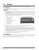
5.2 Teraoka Error Prediction (TEP) Function The DC-530 counting scale includes the DIGI TEP (Teraoka Error Prediction) Function which detects weight variances in sample quantities and calculates the maximum quantity of that piece that can be counted without introducing error. To make the operator’s job easier, the scale’s display will change from green to yellow or red when the maximum safe quantity has been exceeded.
the TARE key. The weight display will now show 0 and the Net and Zero indicator lamps will illuminate. 3. Remove the container, box, or item from the scale. The weight display should show a negative weight value (weight of the tared container, box, or item). 4. To clear the tare weight, press the TARE key. The Net indicator lamp will no longer be illuminated. 5.4.2 Digital Tare, Tare Weight Known 1. Press the REZERO key to zero the scale. 2.
accumulation of tare values. To allow Tare Subtraction, SPEC 45, Bit 3 TARE DECREASE must be set to “1: YES”. 5.4.4 Tare Accumulation 1. Press the REZERO key to zero the scale. 2. At the Counting Mode Screen, place the container, box or item to be tared on the platform and press the TARE key. The Weight Display should now show 0 and the NET indicator lamp will illuminate.
quantity using the numeric keypad before pressing the PCS key. 4. To improve the accuracy of the Unit Weight calculation, add another sample of the same pieces. This second sample should be of a number of pieces equal to or fewer than the first one. Press the PCS key. (NOTE: If Specification 53, Bit 2 is set to the default setting of 1: Automatic, the scale will automatically begin recomputing.
4. You can now begin counting operations by placing a quantity of the pieces to be counted on the platform. The scale will display the number of pieces as well as the Total Weight, based on the Unit Weight you keyed in. To store this Unit Weight in the DC-530’s memory associated with an Item Code so that you can recall it in the future, see Section 6.2.1. 5. To clear the Unit Weight, remove all weight from the scale platter and press the C (Clear) key. 5.5.
7. To print a label showing the total, press the * PRINT key. Figure 5-1. Total Accumulation Label Sample 8. This will also clear the accumulation register. The ACC (Accumulation) indicator lamp will no longer be illuminated. 9. To clear the Unit Weight, remove all weight from the scale platter and press the C (Clear) key. 5.5.
3. Remove Container 1 from the platform. 4. Place Container 2 (full of parts) on the scale. 5. Press the - (Minus) key to subtract the new quantity from the total. The display will show the total which will be the difference between Container 1 and Container 2, then return to the Normal Counting Mode screen. 6. Repeat steps 4 and 5 for all the containers to be subtracted from the total. 7. To print a label showing the total after all the subtractions, press the * PRINT key. Figure 5-2.
NOTE: To perform Negative Counting, SPEC 52, Bit 1 must be set to 1: Yes. This is the default setting. 5.5.7 Counting Out of a Full Container - See Total Amount Remaining in the Container To carry out this operation you must know the tare weight ahead of time. 1. Press the REZERO key to zero the scale. 2. Place the full container on the scale. Press the TARE key. 3. Remove a 10 piece sample from the container and press the PCS key.
1. Press REZERO to zero the scale. 2. Press the TEP key to enter the Teraoka Error Prediction Mode. 3. Count out a number of parts to be sampled and place them on the scale (for example 10 pieces). For maximum accuracy, count the 10 piece sample into your hand and then add the entire sample to the bin at one time, instead of adding them one or two at a time. 4. Enter the sample quantity using the numeric keypad, then press the PCS key.
6. When the sample weight is within the required range, the scale will recompute the Unit Weight and return to the TEP Sampling screen. The scale display will show the new total Weight, Unit Weight, and number of Pieces. It will also now indicate that you have been SAMPLING 2 TIMES. 7. Continue resampling by repeating Step 5, adding another sample below the amount shown on the TEP Mode display.
platform. The scale will display the number of pieces as well as the Total Weight, based on the Unit Weight established by the sampling process. To store this Unit Weight in the DC-530’s memory associated with an Item Code so that you can recall it in the future, see Section 6.2.1.
without error. 2. Press the REZERO key to zero the scale. 3. Place on the platter a quantity of parts to be counted. 4. If the quantity is less than the accuracy limit, the scale will display the count of the number of pieces and reduce the maximum limit to how many more can be counted under the limit. Add pieces up until the quantity limit is reached, then remove the parts from the platter and begin counting again. 5.
5.6.5 TEP Mode - Negative Counting Negative Counting in TEP Mode follows the same procedure as in Normal Counting Mode but you must first establish a Unit Weight by sampling in the TEP Mode. For more information on establishing TEP unit weights, please see Section 5.6.1. For information on negative counting procedures, please see Section 5.5.6 5.6.6 TEP Mode - Clearing Accumulated Data To clear accumulated data, press the * PRINT key. 5.
5.9 Sample, Count and Print a Label NOTE: For this function to be used on the DC-530, an external printer must be connected to the scale. For more information on how to connect an external printer, see Section 7.1. 1. Press the REZERO key to zero the scale. 2. Place the empty bin on the scale and press the TARE key. 3. Place a 10 piece sample of the item in the bin and press the PCS key.
6.0 Scale Programming The DC-530 can store information for up to 200 of the parts you count most frequently, eliminating the need for re-entering data during parts counting and greatly speeding up your counting operations. 6.1 Programming a New Item Code (Item Registration) Before beginning to enter data about an item, you need to know the Tare Weight and the Setpoints you want to set for this Item Code.
If you enter an Item Code that has already been programmed, the display will flash red and the error message ITEM XXX, EXISTING ITEM will appear. Then the screen will ask you if you are trying to update the data associated with this item already existing in memory. If you enter a 1 from the numeric keypad the screen will flash red and show the message: 3. 4. 5. 6. 38 You will then be returned to whichever Counting Mode screen you began with - Normal Counting Mode or TEP Mode.
6.2 Updating the Record of an Existing Item There are two ways to edit or update the data in the record of an Item Code already programmed in memory: from the Counting Mode screen or from the Programming Mode menu. If you want to update an existing item’s Unit Weight from a sampling operation, use the process from the Counting Mode in Section 6.2.1. To update the Tare Weight associated with an existing Item Code, use the process from the Counting Mode in Section 6.2.2.
2. Enter the three digit Item Code for an item you have previously programmed into the DC-530’s item memory and press the # key. The scale will recall the Unit Weight and Tare Weight (if any) previously programmed for ths item. 3. Place the container, box, or item to be tared on the scale platform and press the TARE key. The weight display will now show 0 and the Net and Zero indicator lamps will illuminate. 4. Press the UNIT WEIGHT key.
below, 25 items have already been entered, 175 can still be entered 3. In the Item Programming Screen press the 1 key to enter Edit Item Screen. . 4. At the flashing cursor enter the three digit Item Code for the existing item to be updated and press the # key. The DC-530 will retrieve the data already programmed into memory for this Item Code and display it, moving the cursor to the Unit Weight field 5.
If you press the 1 key to save the changes to the Item Code record the display will turn red and confirm that the record’s data is updating. 9. When the update is done, the display will return to the Edit Item Code Screen. You can enter another three digit Item Code to edit or press the TARE key twice to exit the Program Mode and return to the Mode Menu. 10. Press the 1 key to return to the Weigh Mode. 6.3 Deleting Item Codes 6.3.
4. Enter the three digit Item Code of the item to be deleted, then press the # key to call up that item. The scale will display the information stored for that Item Code. 5. Press the C (Clear) key to delete this Item Code. The display will ask the operator to confirm that he really wants to delete this item. 6. To cancel the deletion of this Item Code, press 9. To complete the deletion of this Item Code, press 1.
delete all data associated with the 25 items in memory. 3. In the Item Programming menu, press the 3 key to enter the Delete All Items mode. The scale will prompt you to confirm that you want to delete all items in memory. 4. To exit without deleting all Item Codes in memory, press 9 and you will be returned to the Item Programming Menu. To confirm the deletion of all Item Codes in memory, press 1.
• Specification 02, Bit 2 - Setpoint Selection, sets whether the setpoint is programmed on the basis of pieces or weight. The default is 0: Pieces. • Specification 02, Bit 3 - Buzzer Output Type, sets whether the buzzer sounds as “Proper” or “Scare/ Over”. The default is 0: Proper. (Example: If the Buzzer Output Type is set to 0: Proper and you have set point values of 50, 75, and 100, a fast beep will sound at 75 and turn off when you reach 100.
7.0 External Devices: Printers, PCs, Scanners and Scales The DC-530 Counting Scale is equipped with three RS-232C ports that allow the scale to communicate with an external printer, a PC, or a barcode scanner plus an additional port for the setpoint output. The DC-530 also offers an option (Part No. 94911) for a second scale channel that will allow you to connect a second platform with up to four 350 ohm load cells. Figure 7-1. DC-530 Ports 7.
DC-530 Side 8 PIN DIN MALE Printer Side 9 PIN D-SUB MALE 7.1.
7.2.2 ZEBRA LP2844 Barcode Printer Set SPEC09 to 0010. The Zebra LP2844 Barcode Printer offers three default label formats for a 60 x 120 mm labels with Code 39 standard barcodes, one for an label without entering or recalling an Item Code, one for an Item Label, and the other for a Total Accumulation Label. Figure 7-3. Zebra Sample Weight and Count Label Without Entering or Recalling an Item Code Figure 7-4. Zebra Sample Item Label Figure 7-5.
7.2.3 Epson TM-U220 Tape Printer Set SPEC09 to 0011. This tape printer uses a default format which is downloaded to the printer when powering up The default format looks like the following:. Figure 7-6. Sample Report Formats for Epson TM-U200 orTM-U295 7.2.4 Epson TM-U295 Ticket Printer Set SPEC09 to 0100. This ticket printer uses the same default format as the Epson TM-U220 tape printer in Section 7.2.3. See Figure 7-6 for a sample of the format. 7.3 Connecting to a PC 7.3.
7.3.3 Pin Assignments The DC-530 counting scale is connected to a PC using a 9 pin D-SUB connector configured as follows: DC-530 Side DIN8 Connector PC Side 9 PIN D-SUB (female) 7.3.4 PIN SIGNAL PIN SIGNAL 2 RXD TXD 5 3 TXD RXD 4 5 GND GND 2 7 RTS CTS 6 8 CTS RTS 7 Data Formats General Data Format All data values are in ASCII format. ID Code The ID Code data string is 12 digits. Set Points Item Set Points are transmitted when an Item Code is recalled from memory.
7.3.5 Output Data Formats With Headers The DC-530 can output two types of headers - Header Codes and Titles. The data transmission string format when output with Header Codes is as follows: HEADER DATA CR HEADER ........... CR LF One data block consists of a header, the data, and a carriage return. A carriage return (“CR”) must appear at the end of the data. A line feed (“LF”) must be added as a transmission termination code.
7.4 Setpoint Connector Your DC-530 has a setpoint output that can be attached to output relays for setpoint control of external equipment when setpoint conditions are satisfied. The device receiving the signal is connected to the DC-530’s Setpoint Connector (see Figure 7-1). To set up the DC-530 to output when the setpoint conditions are satisfied, program the customer specifications as detailed in Section 6.4.
7.6 Remote Scale Channel The Remote Scale option for the DC-530 can be ordered as Rice Lake Part No. 9491. When this option is installed, a remote scale platform can be connected at the right-hand side of the ports and connectors strip on the back of the DC-530. Figure 7-7. DC-530 Ports and Connectors with Remote Scale Channel Connector Installed Pin (Color) Signal BRN RS+ BLU RS- GRN IN+ YEL IN- WHT VEX+ RED VEX- BLK FRAME GND Table 7-4. Remote Scale Channel Pin Configuration 7.6.
7.6.2 Remote Platforms Available Platform Capacity Platform Dimensions 100.00 lbs 13" x 17" (DIGI S-SL Platform) 250.00 lbs 17" x 21" (DIGI S-TL Platform) 500.00 lbs 17" x 21" (DIGI S-TL Platform) 1500.0 lbs 24" x 28" (DIGI S-UL Platform) 2500.0 lbs 36" x 36” or 48" x 48" (DIGI Summit 3000 Platform) 5000.0 lbs 48" x 48" (DIGI Summit 3000 Platform) 10000.0 lbs 48" x 48" or 60" x 60" (DIGI Summit 3000 Platform) 25000.0 lbs 42" x 72" or 60" x 84" (DIGI Summit 3000 Platform) 50000.
8.0 8.1 Appendices Error Message List The DC-530’s alphanumeric display allows for detailed error messages. Use Table 8-1 below to find the error message, possible causes for the error and ways to correct the problem. If these suggestions fail to correct the situation, please contact your DIGI dealer for assistance.
8.2 Troubleshooting Table 8-2 shows some potential problems that might arise while using your scale, their possible causes, and the corrective action that can be taken to resolve them. Error Message The scale does not power on. Possible Causes Corrective Action The main switch on the bottom of the scale is off. Turn on the main switch. The AC cord is not completely plugged in. Push the connector for the AC cord firmly into its socket. The fuse is burned out. Replace the fuse.
8.3 Specifications Operating Conditions • • Operating TemperatureOperating Humidity - -10°C ~ +40°C (OIML) 15%~ 85% RH Electrical Specifications • • • • • Power Source AC117/100V Charge Current 800 mA Main Board Backup Battery-Lithium rechargeable battery for data protection Clock Built-In Real-Time Clock Memory 200 Items Unibloc Force Cell Specifications • • Input Sensitivity Minimum Impedance - Resolution Specifications • • • Display Device Internal Resolution Display Resolution - 0.
9.0 DC-530 Limited Warranty Rice Lake Weighing Systems (RLWS) warrants that all RLWS equipment and systems properly installed by a Distributor or Original Equipment Manufacturer (OEM) will operate per written specifications as confirmed by the Distributor/OEM and accepted by RLWS. All systems and components are warranted against defects in materials and workmanship for one year. RLWS warrants that the equipment sold hereunder will conform to the current written specifications authorized by RLWS.