
Installation manual


10
5. Press the
Select
key to place the SDCP in direct communication with the selected modem.
The LCD displays the Top-Level menu for the selected modem. In addition, the Front Panel LED on the
modem’s faceplate and the OK LED on the SDCP light.
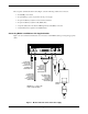
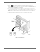
6. Once you have determined that the modem is installed properly and completed its power-up self-test,
rotate the circuit pack lock until it covers the faceplate latch (Figure 3) and tighten the retention screw on
the circuit pack lock. This prevents the modem from accidently being removed once it is installed in a
carrier.
7. Configure the modem as described in the Selecting Factory Configuration Options section.
Figure 3. Circuit Pack Lock