
Installation manual


8
Removing and Replacing Model 3910 Modems
To remove and replace a Model 3910 modem, perform the following steps:
1. Make sure the modem is offline, and press the modem’s rear panel power switch to the OFF position.
2. Disconnect the power cord from the ac power outlet, and then disconnect the dc power cable from the
connector on the rear of the modem.
3. Disconnect the dial and leased-line modular cords from the modem’s rear panel.
4. Disconnect the DTE interface cable from the modem’s rear panel.
If the modem is to be removed for service, return it using the procedures described in Government
Requirements and Equipment Return.
5. Install the replacement modem as described in the Model 3910 Modem Installation section, and configure
it the same way as the modem being replaced.
Model 3911 Modem Installation
CAUTION
If the Model 3911 is removed from the carrier, always use a
ground strap when handling the modem. Always store the
Model 3911 in an antistatic bag when it is removed from the
carrier.
The Model 3911 is designed for installation in a COMSPHERE 3000 Series Carrier which supplies both the
operating power and the leased and/or dial network connections. For correct power, DTE, dial-line, leased-line,
and network management cabling information, refer to the COMSPHERE 3000 Series Carrier, Installation
Manual.
The COMSPHERE 3000 Series Carrier has 17 slots which can hold up to 16 modems and one shared diagnostic
unit (SDU). The SDU is required when the modems in the carrier are controlled by an NMS, or when multiple
carriers in a cabinet configuration are to be controlled by a single shared diagnostic control panel (SDCP). The
SDCP of the COMSPHERE 3000 Series Carrier is the user interface to the Model 3911 modem. A single SDCP
can control up to eight carriers containing up to 128 compatible modems.
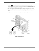
The installation of a Model 3911 varies slightly if an SDCP is installed on the front of the carrier. To install a
Model 3911 modem into the carrier without an SDCP, perform the following steps:
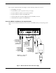
1. At the rear of the carrier, install the rear connector plate. Make sure the plate uses the same slot position as
that intended for the modem.
Loosely fasten the plate. This allows for slight adjustments later when installing the modem.