
Manual

D
D
i
i
g
g
i
i
l
l
e
e
n
n
t
t
P
P
m
m
o
o
d
d
O
O
C
C
1
1
™
™
O
O
p
p
e
e
n
n
C
C
o
o
l
l
l
l
e
e
c
c
t
t
o
o
r
r
O
O
u
u
t
t
p
p
u
u
t
t
M
M
o
o
d
d
u
u
l
l
e
e
B
B
o
o
a
a
r
r
d
d
R
R
e
e
f
f
e
e
r
r
e
e
n
n
c
c
e
e
M
M
a
a
n
n
u
u
a
a
l
l
®
www.digilentinc.com
Revision: 04/12/05
215 E Main Suite D | Pullman, WA 99163
(509) 334 6306 Voice and Fax
Doc: 502-062 page 1 of 1
Copyright Digilent, Inc. All rights reserved. Other product and company names mentioned may be trademarks of their respective owners.
Overview
The Digilent PmodOC1 Open Collector Output
Module Board (the OC1™) can drive high
current devices using MMBT3904 output
transistors. The transistors are driven by logic
signals from a Digilent system board.
The transistors function as switches and can
drive relays and turn on LEDs, motors, and
other outside devices.
Features include:
• four 100mA (200mA max) MMBT3904
transistors
• a 6-pin header and 6-pin connector
• four output clamp diodes
• 40V voltage threshold
• small form factor (0.75” x 0.80”).
Functional Description
Each transistor functions independently of the
others, so they can be used individually or
simultaneously.
Each transistor has a collector that conducts
current between an outside device and a
ground connection established by the OC1.
When a transistor is turned on, current flows
through the circuit connected to the
corresponding pin on J2.
The OC1 has four output clamp diodes that
prevent damage to the transistors by
dissipating fly-back current from inductive
loads.
The OC1 has a 6-pin header for easy
connection to a Digilent system board. Some
system boards, like the Digilent Pegasus
board, have a 6-pin header that can connect to
the module with a 6-pin cable. To connect the
OC1 to other Digilent system boards, a Digilent
Modular Interface Board (MIB) and a 6-pin
cable may be needed. The MIB plugs into the
system board, and the cable connects the MIB
to the OC1.The OC1 also has a 6-pin
connector for easy connection to the Digilent
Pmod connector module.
For more information, see the reference
manual at www.digilentinc.com
.
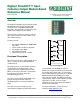
GND
Vcc
J1 Connector
P1
P2
P3
P4
OC1 Circuit Diagram
J2 Connector
P1
P2
P3
P4