
Datasheet
1300 Henley Court
Pullman, WA 99163
509.334.6306
www.digilentinc.com
PmodLS1™ Reference Manual
Revised February 13, 2015
This manual applies to the PmodLS1 rev. B
DOC#: 502-068
Copyright Digilent, Inc. All rights reserved.
Other product and company names mentioned may be trademarks of their respective owners.
Page 1 of 2
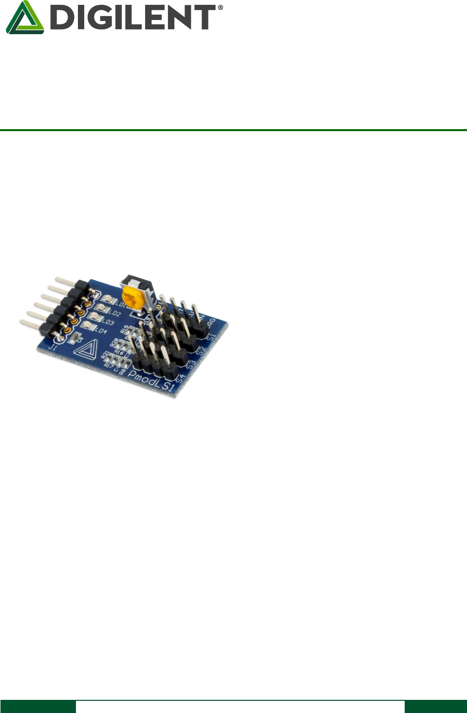
Overview
The Digilent PmodLS1 allows users to receive signals from multiple optical sensors, such as the popular
combination of an IR LED with an IR sensor used in line-following robots.
1 Functional Description
The PmodLS1 is designed to be used with up to four sensors containing an infrared LED and an infrared-sensitive
photo-transistor, such as the IR Proximity Sensor available from Digilent. When using Digilent's sensors, refer to
the print on the board indicating the wire color for the correct orientation of the wire. If third-party sensors are
used, refer to the board schematic available at www.digilentinc.com for the proper connection of the LED and
photo-transistor.
The module uses analog comparators to determine when the infrared detectors have sensed more infrared light
than the threshold limit. The sensitivity of the sensors can be adjusted by adjusting the onboard potentiometer.
2 Interfacing with the Pmod
The PmodLS1 communicates with the host board via the GPIO protocol. By the Pmod design, each of the outputs
will only send a logic 1 value when its sensor is picking up more optical light than the threshold limit. When the
The PmodLS1.
Up to four attached sensors
An adjustable gain (threshold) for the
sensors
Features include: