
Datasheet

PmodLS1™ Reference Manual
Copyright Digilent, Inc. All rights reserved.
Other product and company names mentioned may be trademarks of their respective owners.
Page 2 of 2
light level is lower than the threshold limit, the output will instead send a logic 0 value. This style can then be
connected to an interrupt within the system board for an ideal usage, although this is not necessary.
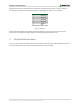
Pin Number
Description
1
Sensor S1
2
Sensor S2
3
Sensor S3
4
Sensor S4
5
Ground
6
VCC
Table 1. Pin descriptions.
Any external power applied to the PmodLS1 needs to be between 2.7V and 5.5V to ensure that no internal
components on the Pmod are damaged. Digilent recommends operating this Pmod at 3.3V.
3 Physical Dimensions
The pins on the pin header are spaced 100 mil apart. The PCB is 1.375 inches long on the sides parallel to the pins
on the pin header and 0.8 inches long on the sides perpendicular to the pin header.